


208U-3A
*Click on the photo to see it in a larger size.
Updated : Mar 29 2009
COLLINS 208U-3A HF linear amplifier
Purchased report
When I looked at the Collins 208U-3A during the Dayton Hamvention in May, 2004, I had made my decision to buy it just
at the time.
However, the delivery was slipped away eight months because of four months to get approving for the export with the US
export control since the 9.11 terrorism.
Although I expected the arrival before the Christmas, I could get it as a late gift under the snowing in next January
because of the additional delay to transportation by the ship.
After inspecting the delivered system, I found that the system was different from my selected system, conditioned in
the worst with replacements almost original parts and PCB modules by damaged PCBs handled by hobbyists before
shipment.
By too many damaged parts in replaced PCBs, I had to repair them unfortunately.
I had however understood this chance should be very happy for me to enjoy the challengeable collection into many
portions.
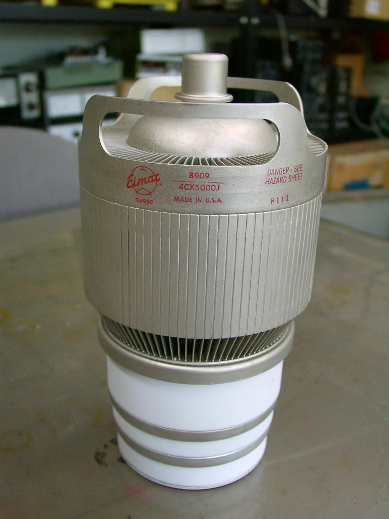
As the final tube, 4CX5000J (right), is quite difficult to purchase additionally,then the testing to run had been done
using the compatible functional tube, ,8F45R made in Japan. After severe searching on the eBay, the rare tube 4CX5000J
to find had been won in June, 2008.
I appreciate the contribution of the eBay quite well.
I had bought two systems of 208U-3A considering with the parts usage (left).
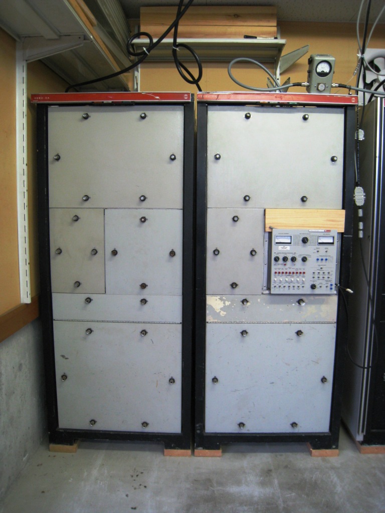
Just arrived 208U-3A system (left) and the system carried out, from the back of the stock room in the
Fair Radio Sales, to be inspected for my purchase.
The owner (right) bothered to handle the forklift truck.


The final amplifier unit
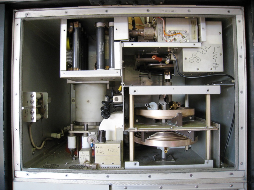
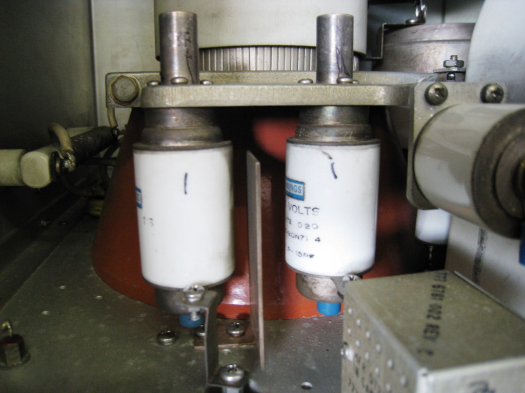
The tube 4CX5000J in the back area, and small vacuum capacitors for the neutralization and the NF adjustment.


The non-inductance resistance is for the tuning purpose.

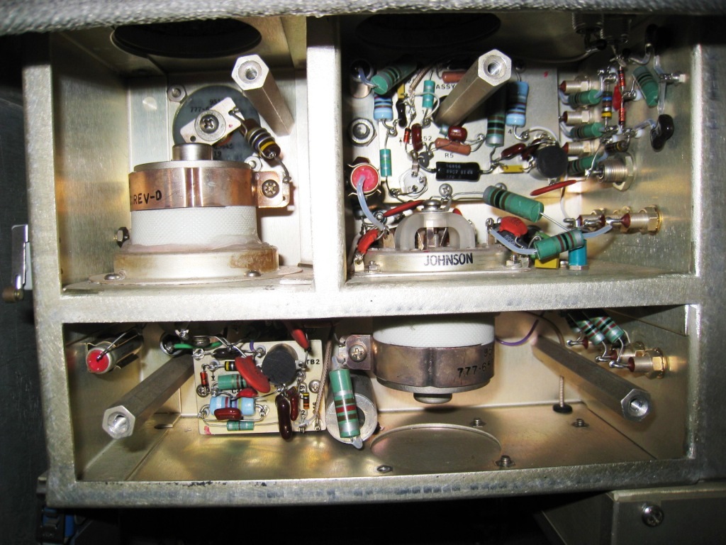
The top view of the final tube (left) and the tank circuit for the final stage (right)

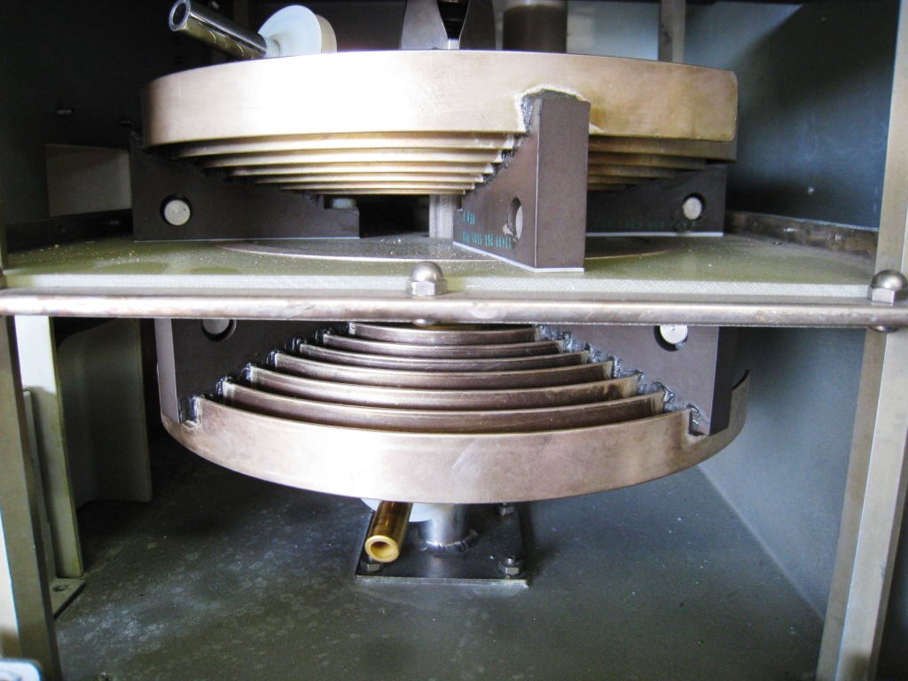
The tuning circuit for the final stage (left) and the loading coil (right)

Connectors for the antenna switching unit are the HN type(left).
The driver unit which is configured by three stages with the grounded base transistor as the first stage and two tubes
of 4CX350A operated as the A class operating amplifier in the second and third stages.
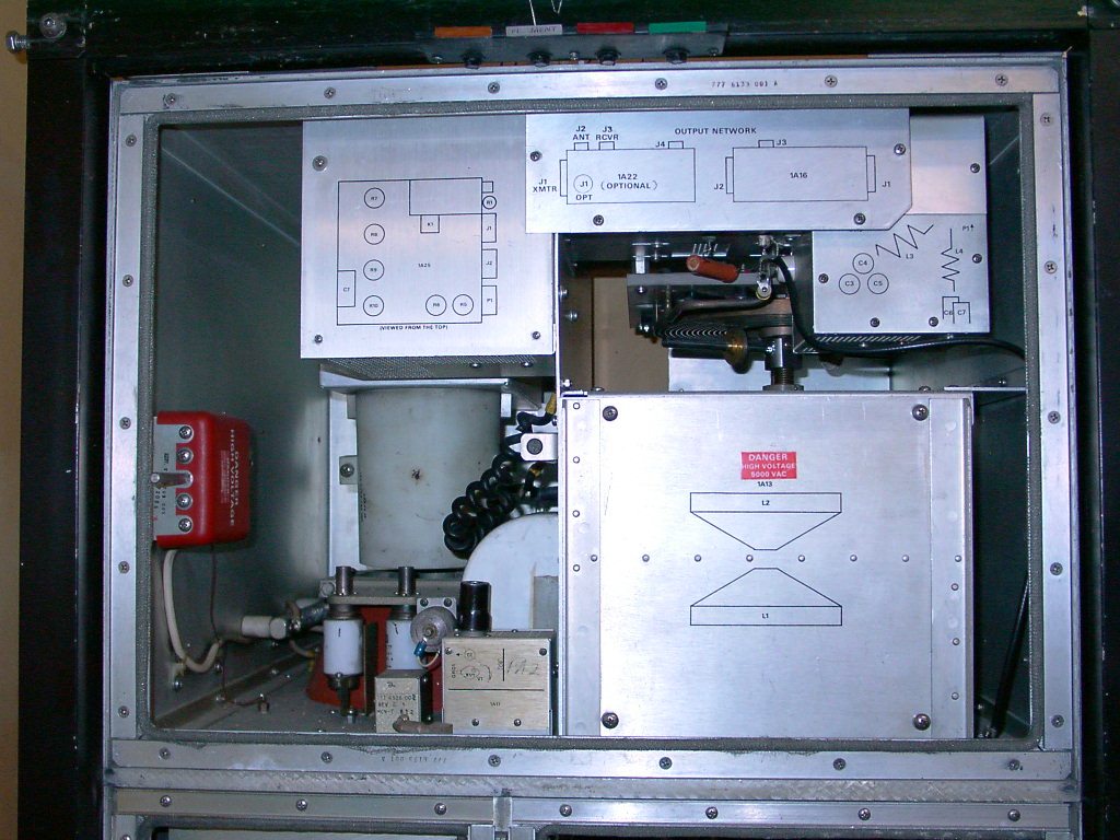
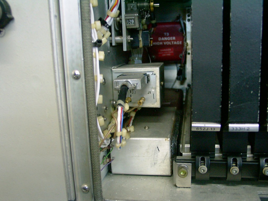
The top view of the connection point of the input and the output (left) with the switch unit for the antenna using the
large size vacuum relay for TX or RX.
Antenna Switchi Assembly (Lift) Driver Assembly :2 x 4CX350A and A class ampliers both of two steps..(right)
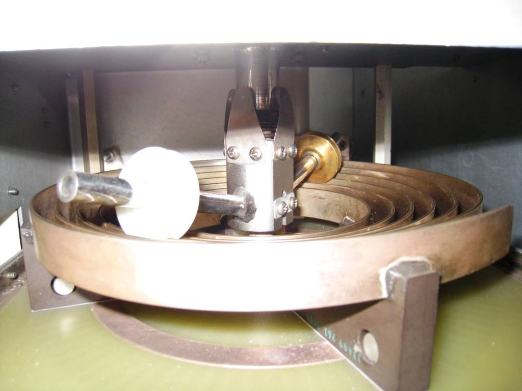
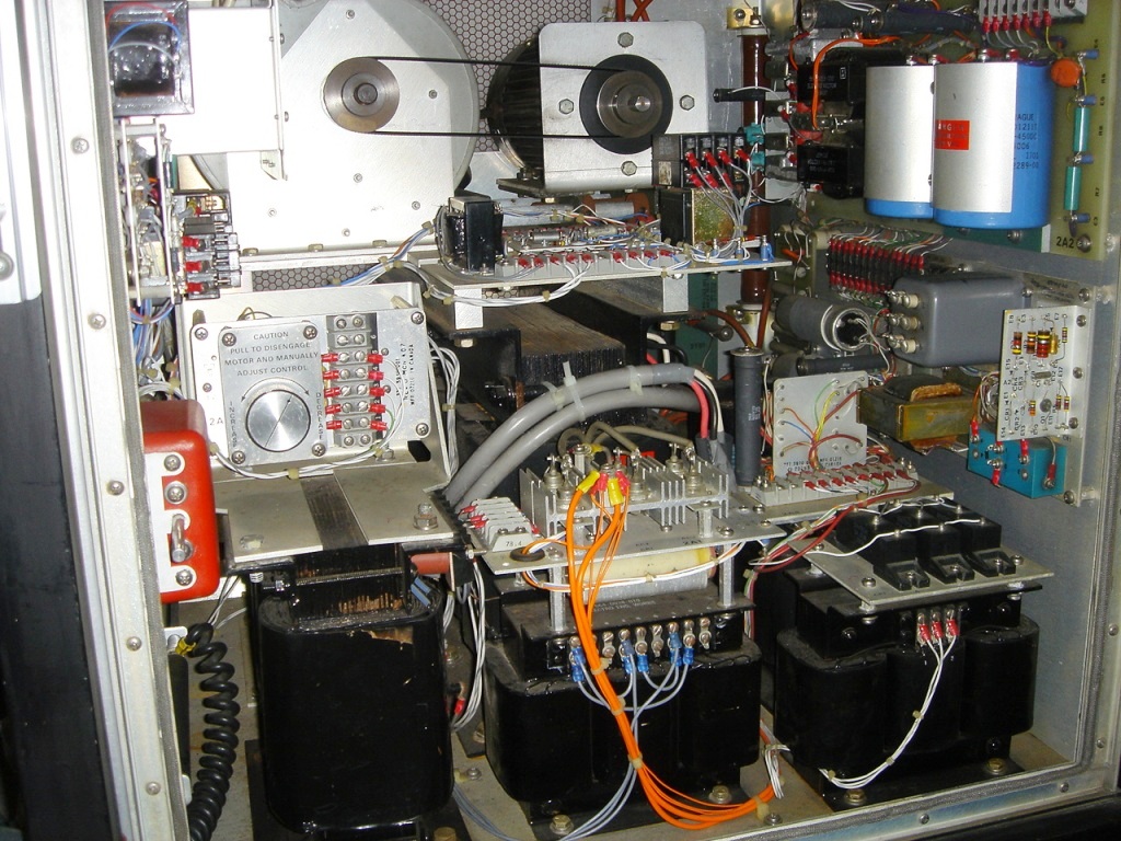
The control unit (left) and the gear mechanics with the servo motor for rotating the tank coil. (right)
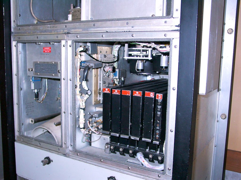

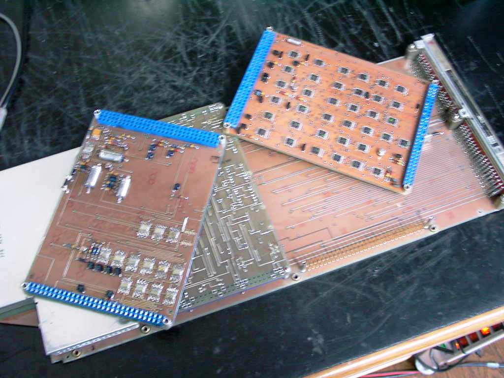
The back plane for connecting the control PCBs (left) and the inserted PCB units (right).
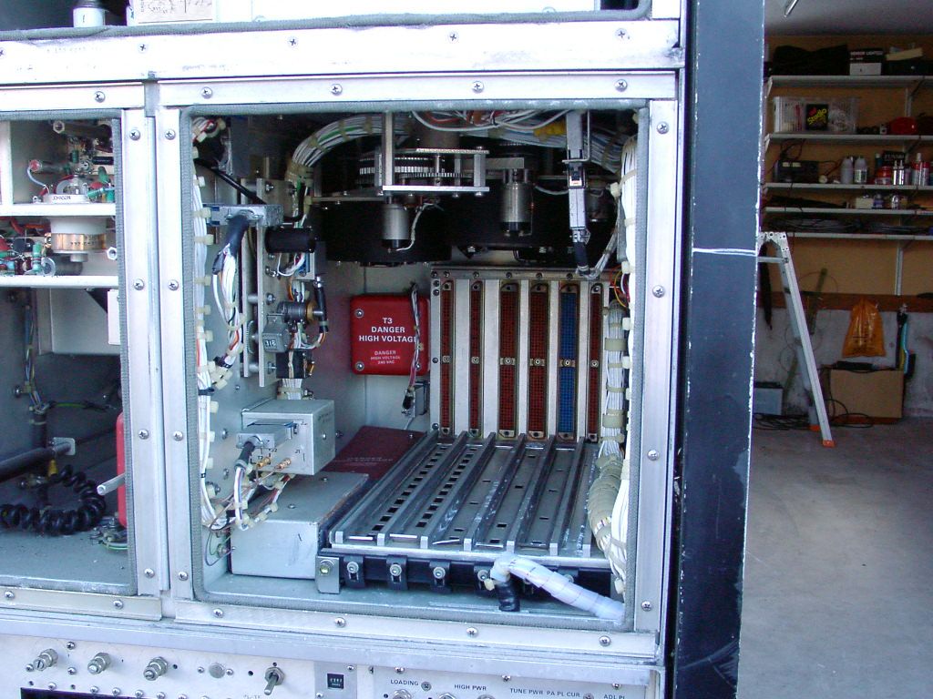
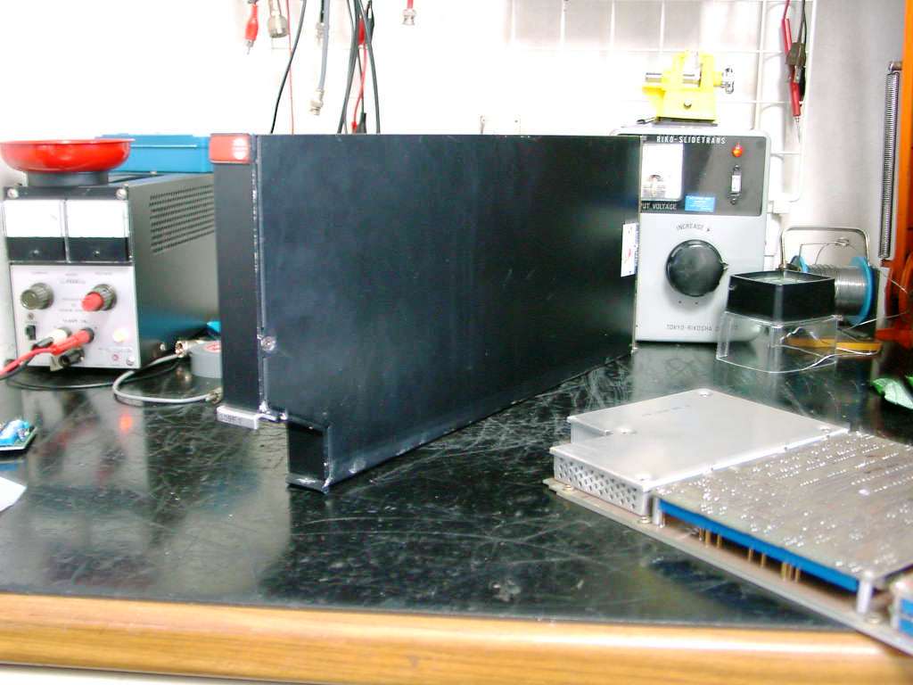
The power supply unit (left) and the large transformer for the high voltage in the central back and the motor to handle the cooling fan.

The stabilizer unit for the heater voltage, even though there is a knob (left).


It is the fault tube 4CX5000J which has been purchased expensively as a new one in the Dayton Hamvention in 2007
unfortunately (left).
The really new one which has been gotten at the eBay just after coming back from the Dayton Hamvention in May 2008 is
very valuable and usefu(right).


The testing set 975K-4 (left) and the testing panel (right) in the hard baggage should be must to repair the system. More than one year were needed to find this set.
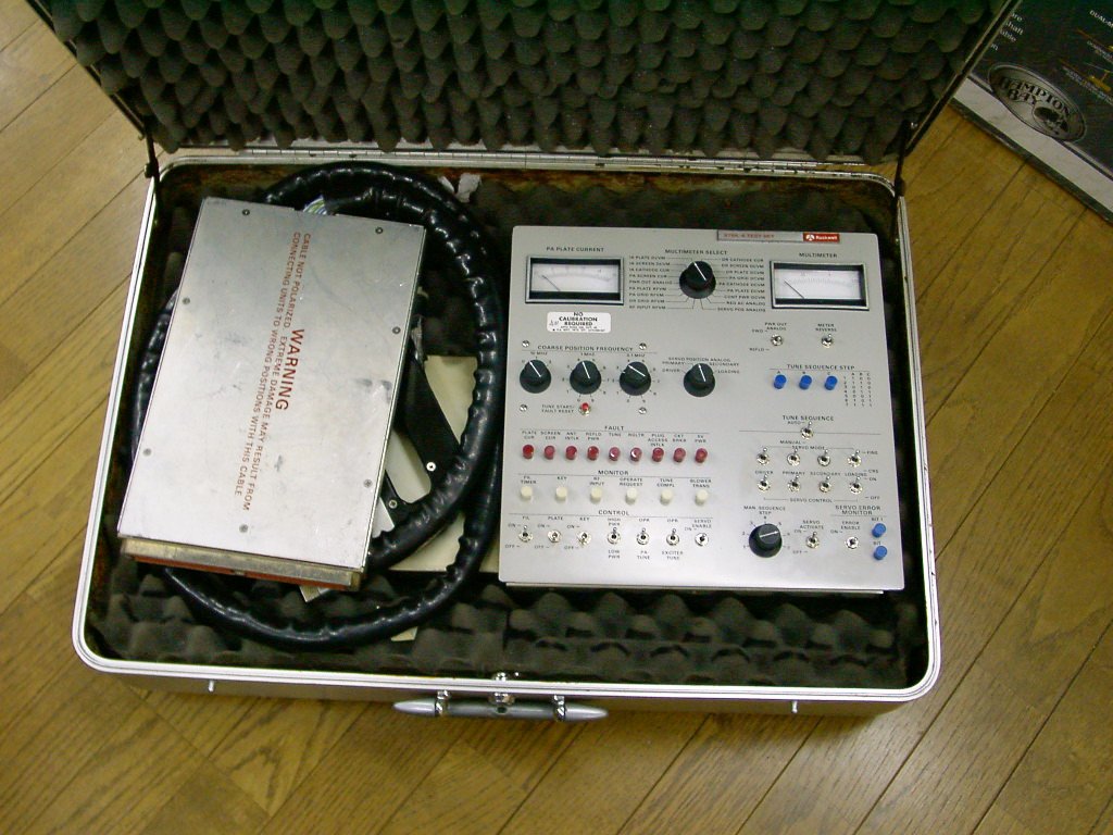

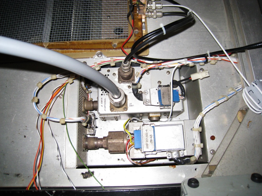
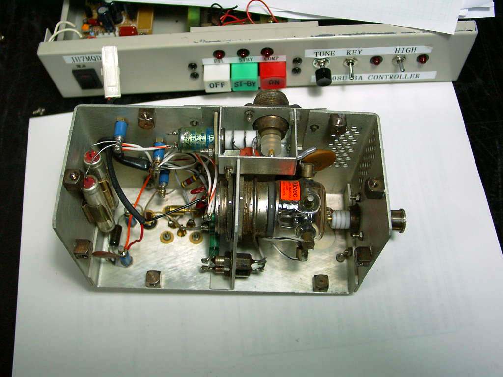
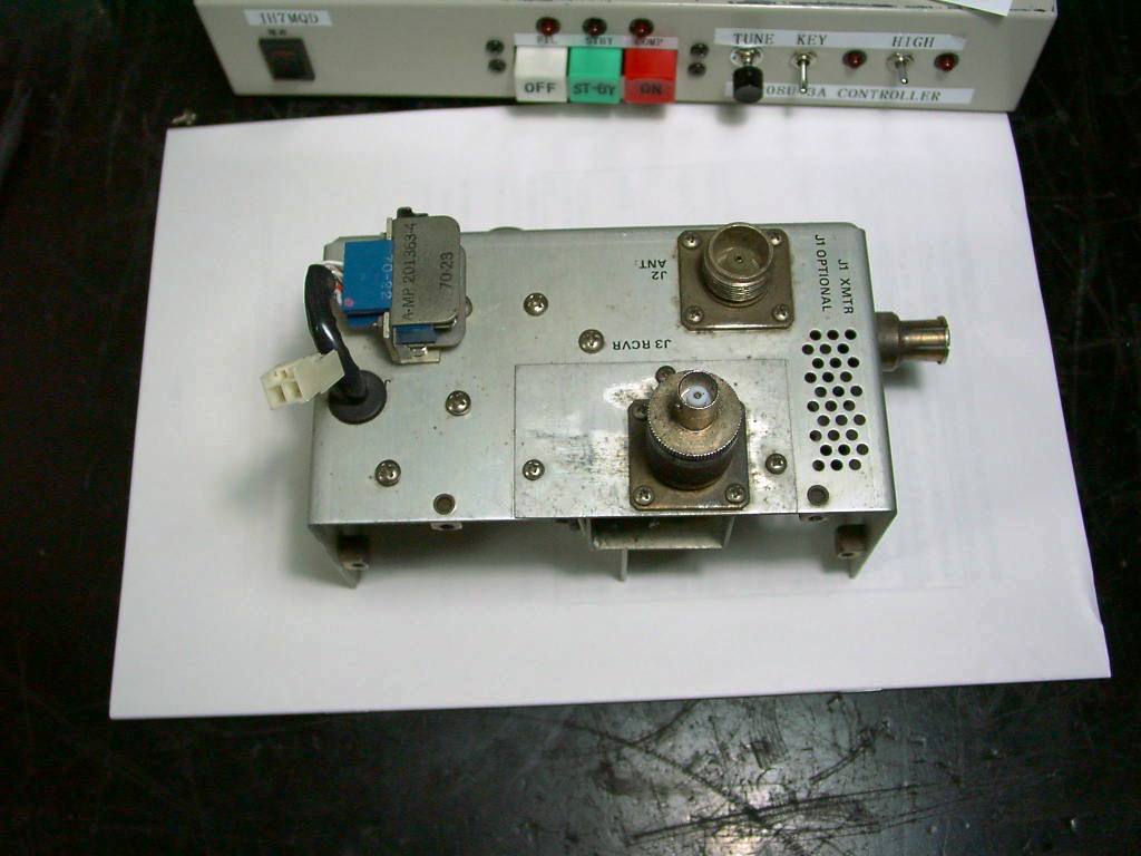
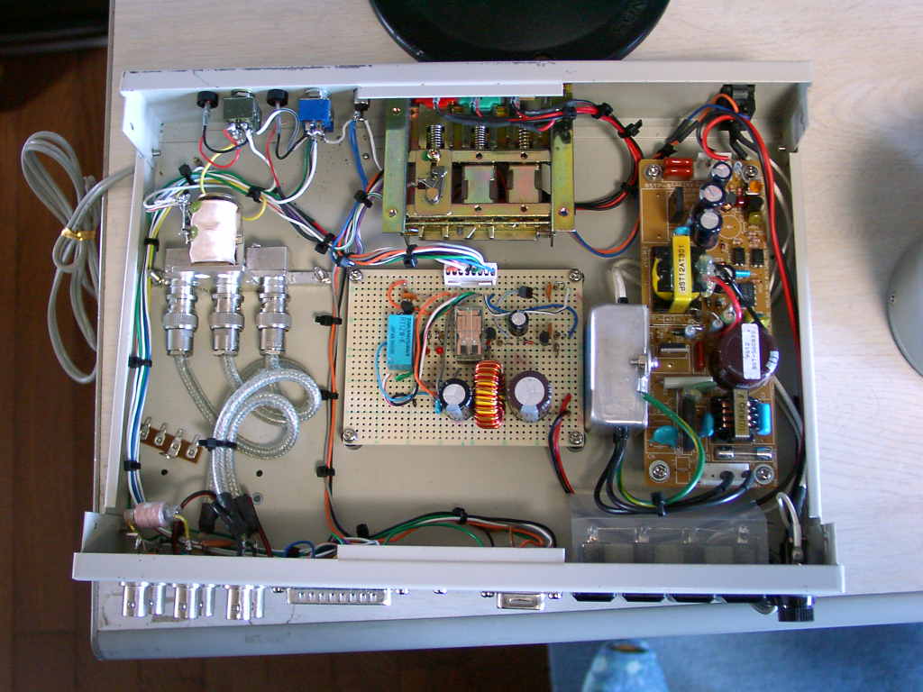
The testing panel (left) and the additional bread of the frequency counters inside of the panel (right) modified for the remote control purpose.
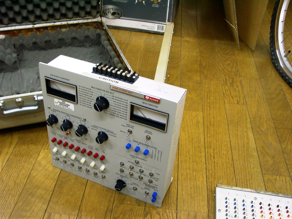

The modified testing panel to control remotely (left) and the controller circuit board (right).
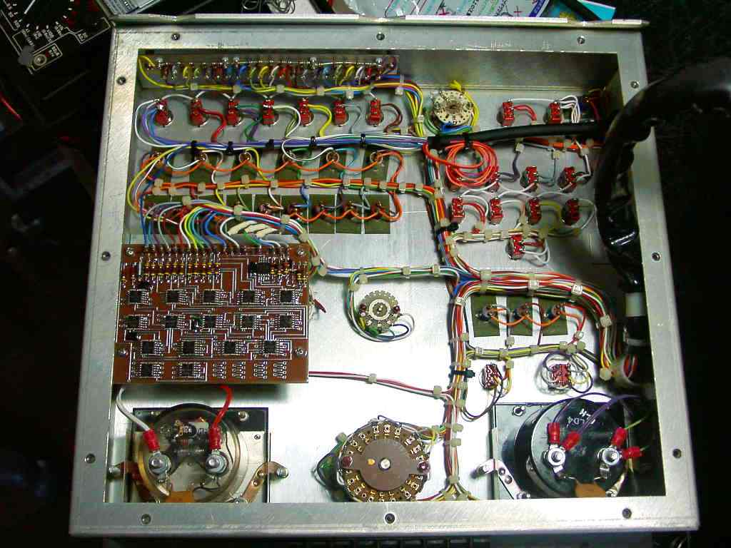
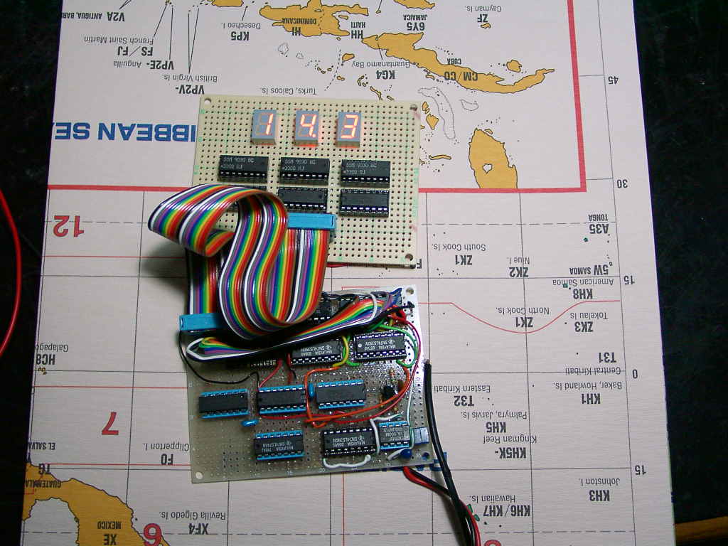
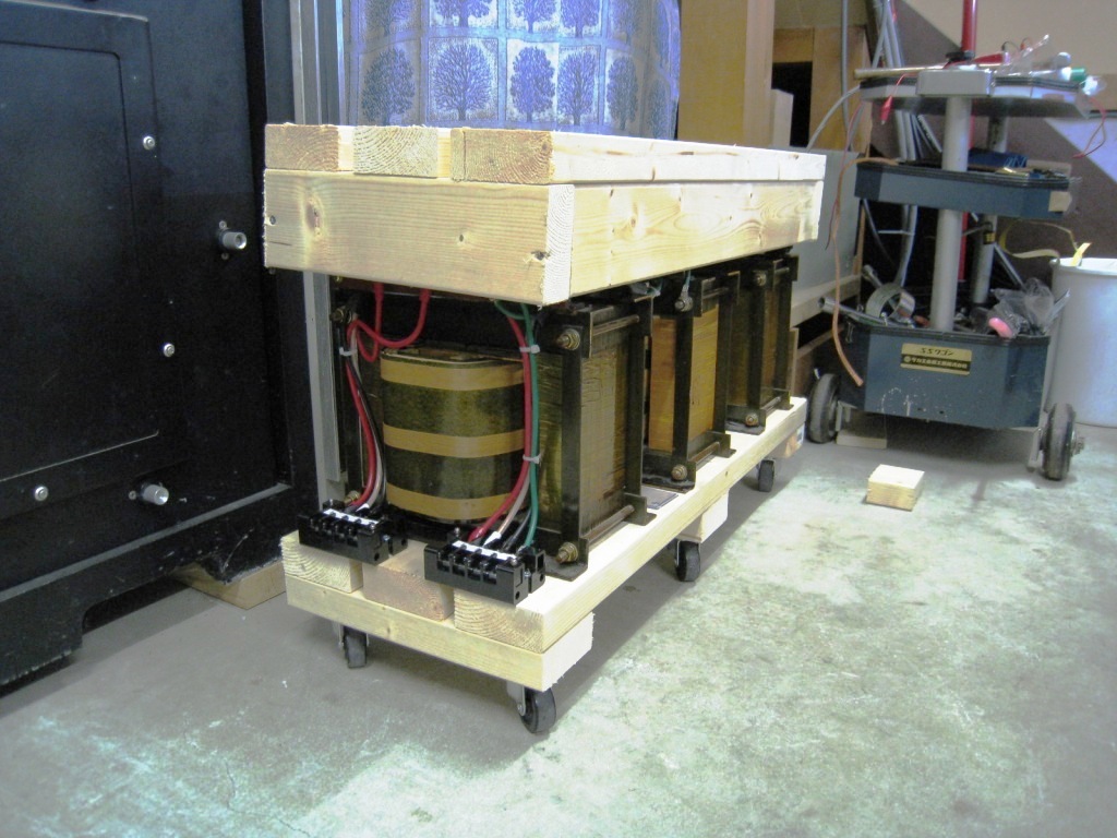
The home-brewed PCB of the frequency counters (left) and the transformer sub-system for the three phased AC line
configured by cheaper three transformers
of the single phase made by DIY trials (right). It is useful to protect against activating the leakage breaker.
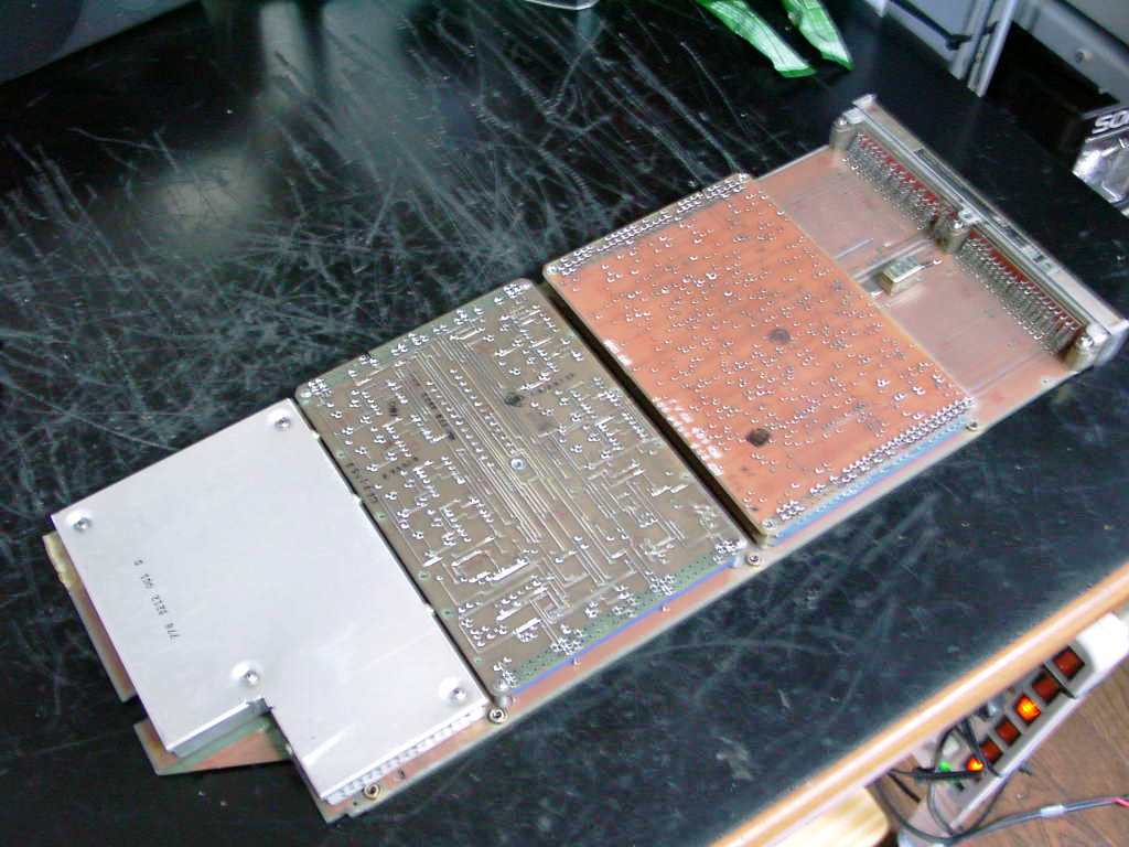
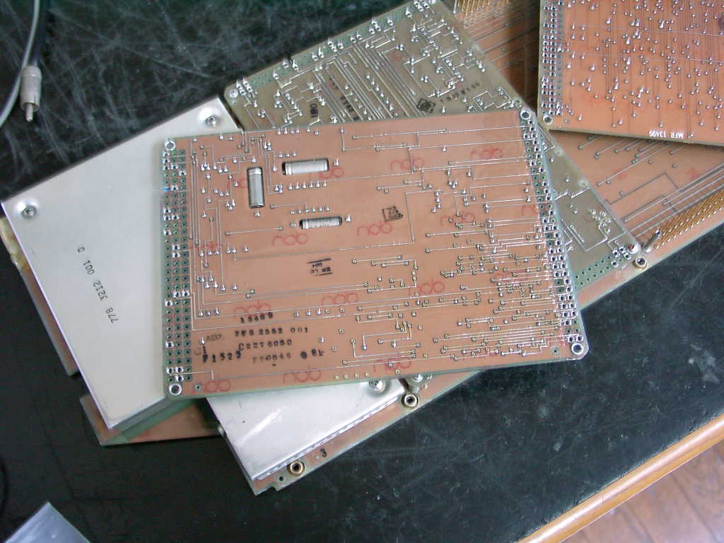
The controller boards are sealed in whole by the epoxy resin in order to eliminate the influence of the moisture.
The grinder is convenient to remove the epoxy of the portion to prove for testing..
Each PCB unit is repaired under injecting the simulated signal with the specified voltage on the work bench, because
the check to test them in the operational state is very difficult.
There are many parts and symbols that are not understandable on the PCB. Thus, the schematic diagram is supportable to
identify the parts with some supposing.
Under these hard situation to repair, initial repairing procedure was time consumed working like more than a month per
PCB, that is, almost 50 hours and more for each board.
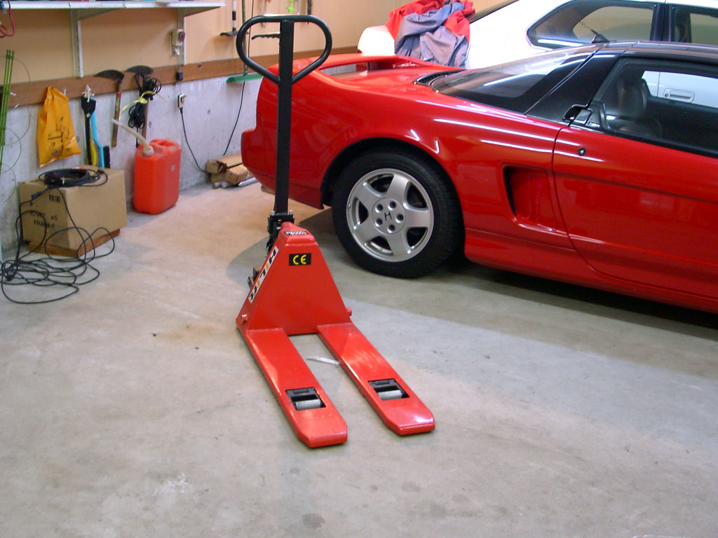
The palette track is useful to move the amplifier system more than 800kg by single myself and my favorite red car can
output more than 200 horse power (left).
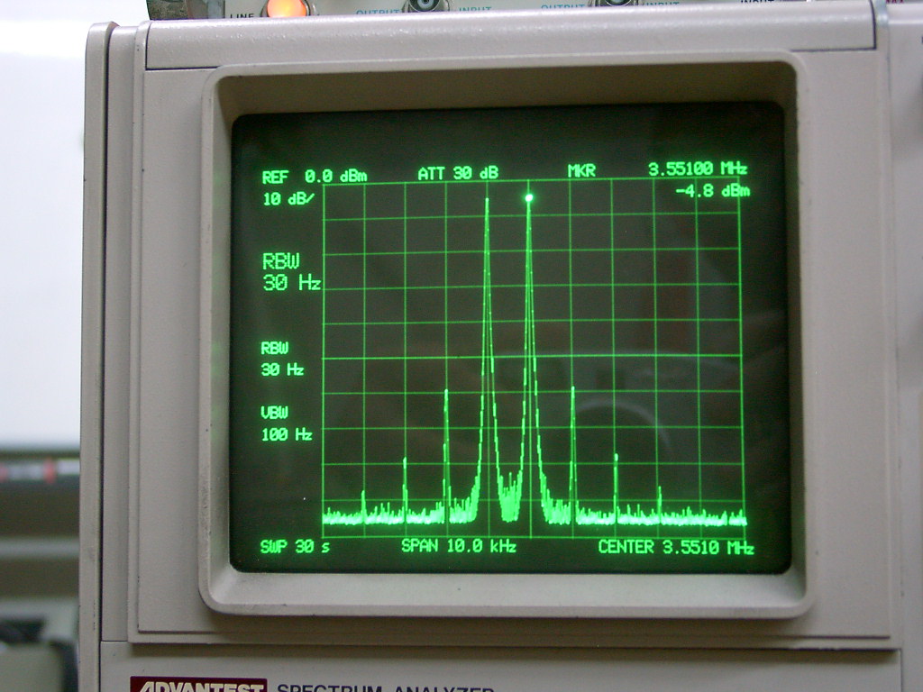
The spectrum analyzer describes the IMD3 during outputting the 1kw from the amplifier system.
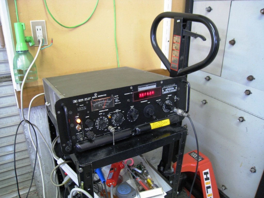
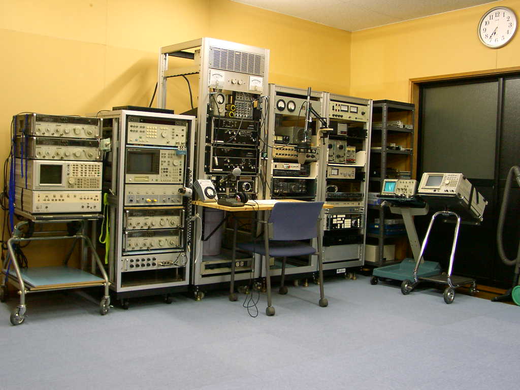
The signal generator, HP8040B of the military version for maintaining the amplifier system (left) and my testing bench with the spectrum analyzer TR-4171, the spectrum analyzer & network analyzer HP-4195 and the two channel type signal generator HP-3326 (right)