


HF-8014A
*Click on the photo to see it in a larger size.
Updated : April 10 2009
ROCKWELL COLLINS HF-801HF 4ch exciter 100mW
Details
The HF-8014A exciter unit can transmit the signal powered by an output of 100mW through four channels concurrently
with USB, UUSB, LSB and LLSB.
The HF-8014A can be connected to the power amplifier like the Rockwell Collins HF-8020, HF-8021, HF-8022 or
HF-8023.
The HF-8021 (the successor to the 208U-3A amplifier) and HF-8022 (the successor to the 208U-10A amplifier) have
configured the affordable amplifier tubes that have
the performance of the lower distortion under the concurrent operation with four channels.
Otherwise, we should develop the control circuit unit for using a different amplifier system.
There were reports that the DDS sub-system of HF-8014A was only for the late version, which had caused the DDS to
malfunction so often.
The functional specification of HF-8014A is as follows:
1)The operational frequency range is between 2MHz and 30MHz.
2)The available mode is for operating on USB, UUSB, LSB, LLSB, AM or CW.
3)The quality figure of IMD3 is more than -50dB/ 200mW PEP operating on the single channel.
It should be recommended to attach the low-pass filter for operating of the ham radio communication,because the band
width of SSB is a little wide like
150Hz to 3150Hz under 3dB down.
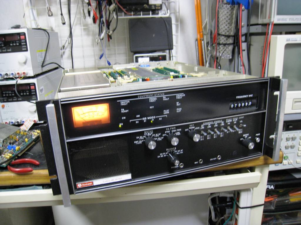
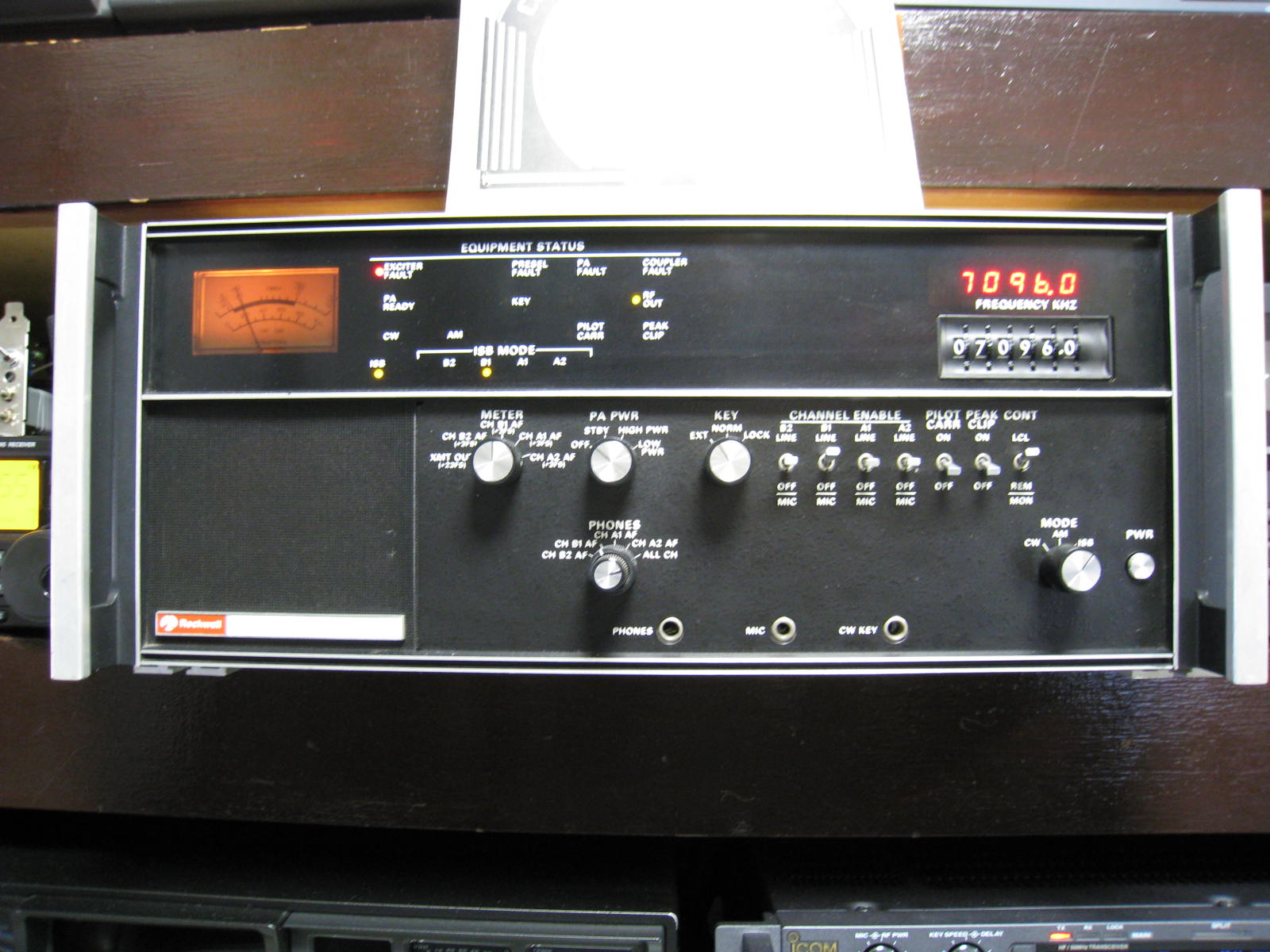
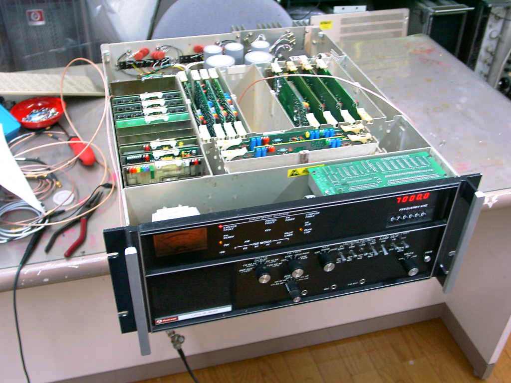
The frequency counter in the photo of right-hand is optional.
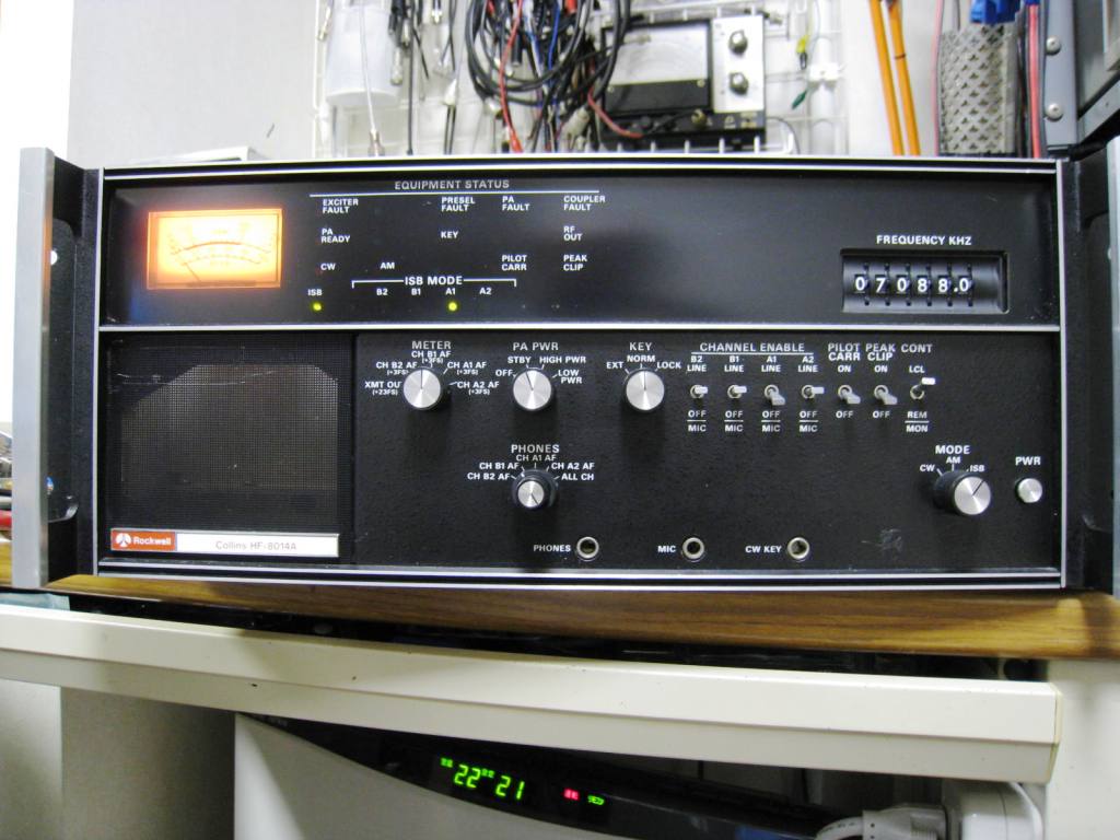
The DDS version of HF-8014A(left)
The PLL version of HF-8014A with installed four channels(right)
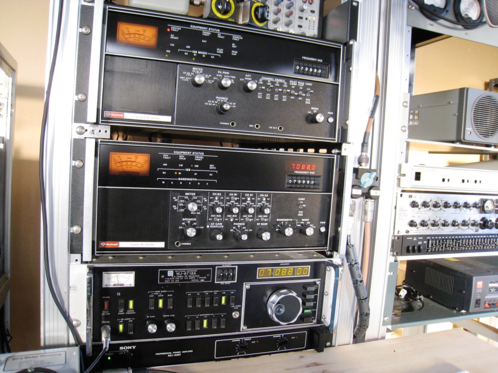
From the top, HF-8014A, HF-8054A and WJ-8718A.(left)
The PLL version of HF-8014A.(right)
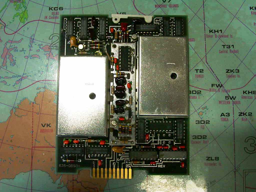
The inside of the DDS version�fs HF-8014A with two channels with control PCB.(left)
The synthesizer is configured by the DDS architecture. (It's so rare in Japan.)(right)
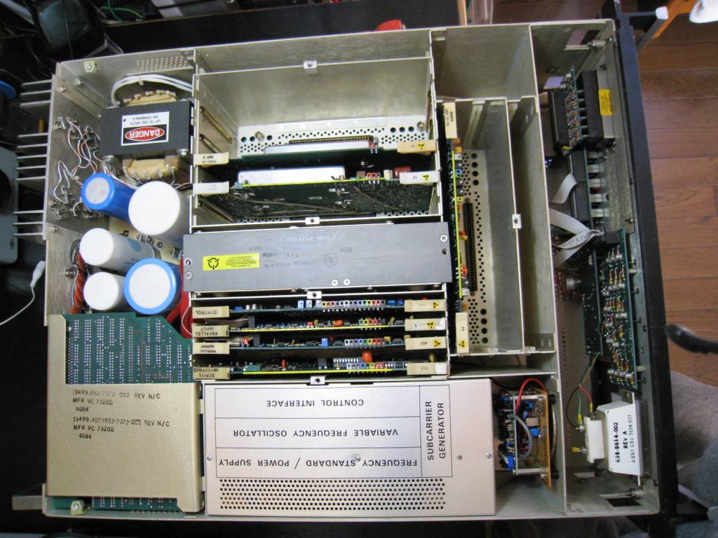
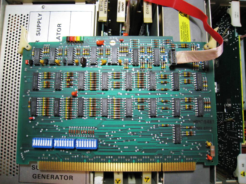
The synthesizer is configured by the PLL architecture with lots of PCB.(left)
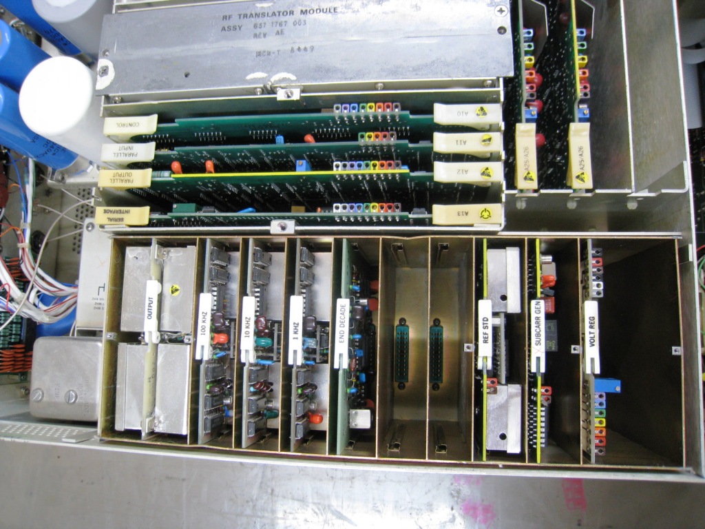
There are many decade boards like 10Hz, 100Hz, 1KHz, 10KHz and 100KHz in the PLL PCBs.(right)
The rotary encoder unit (Right), and the switch unit for the frequency standard. (Left)
The Output circuit PCB of the synthesizer.(right)
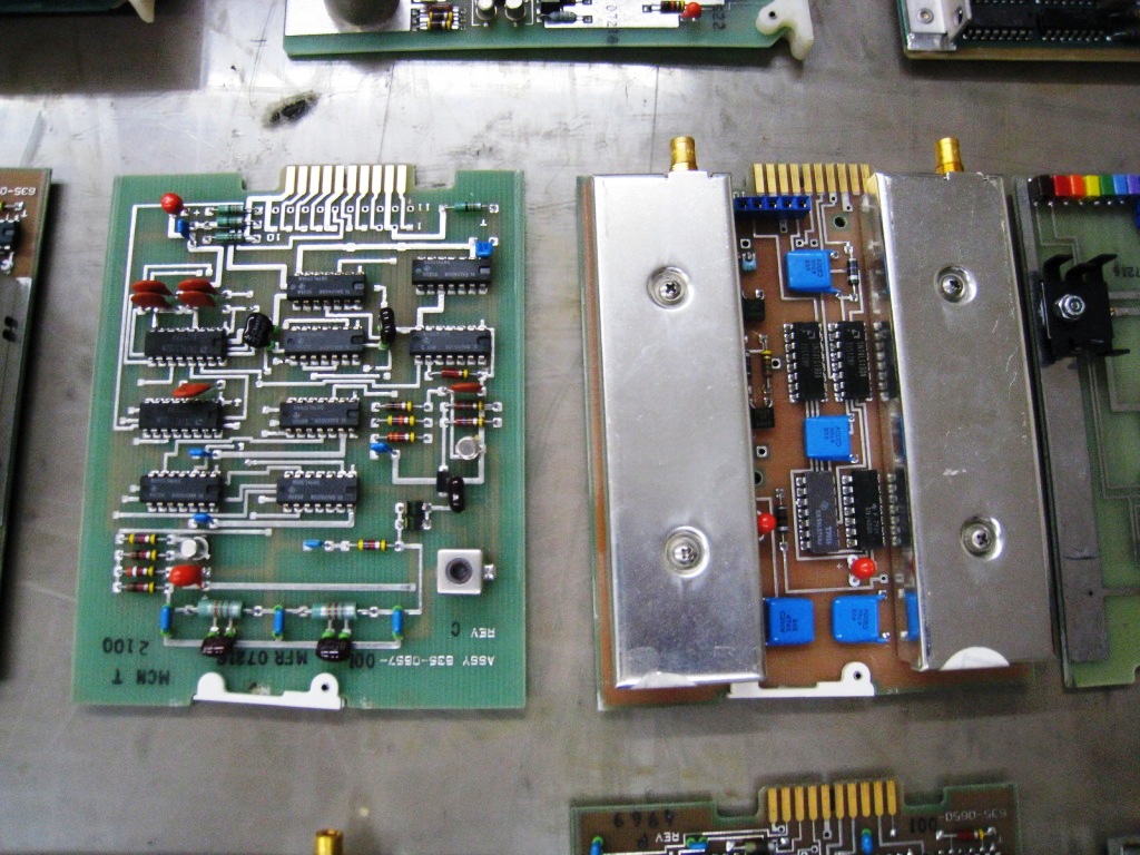

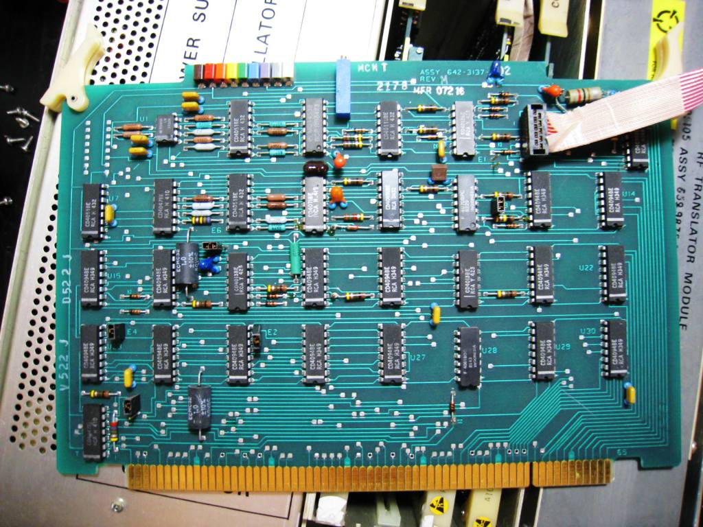
The Control Interface circuit PCB of the synthesizer(left)
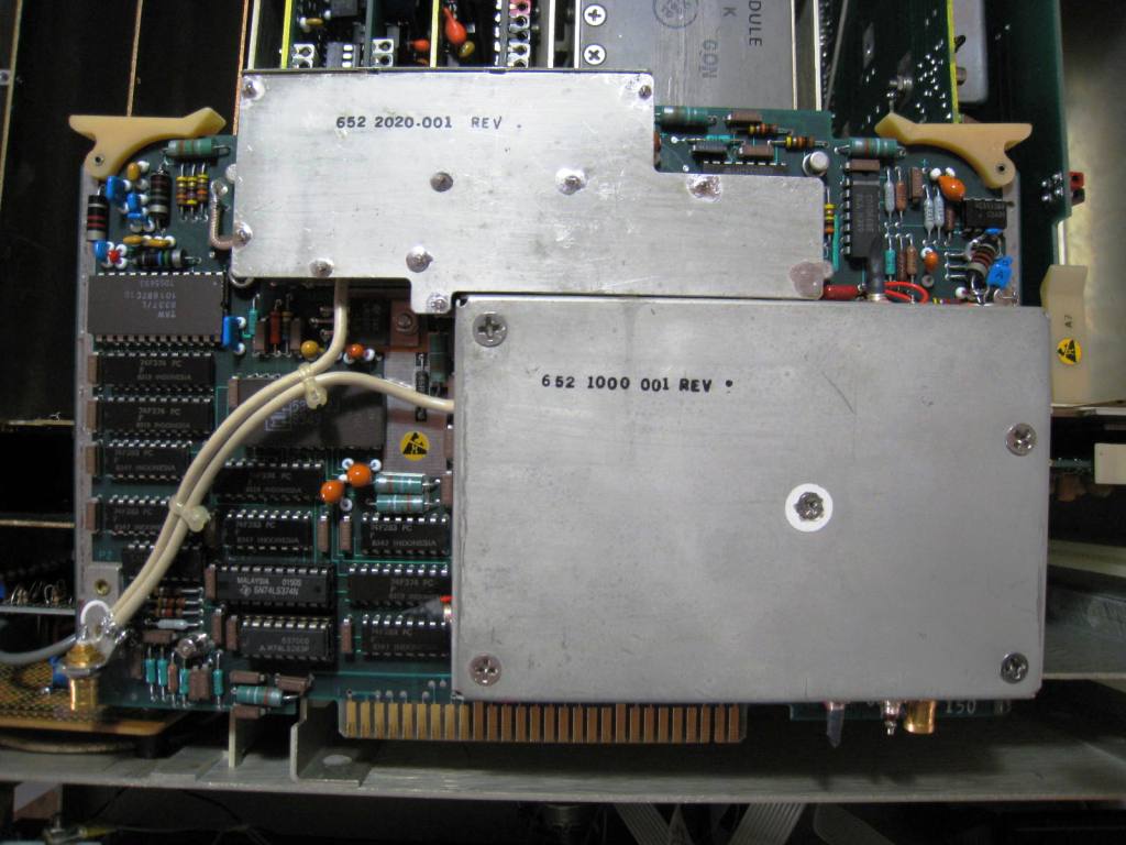
The VFO/ VCO module PCB.(right)

The Standard Signal generator and the Regulator PCBs in the DDS cage.(left) The Audio amplifier PCB.(right)


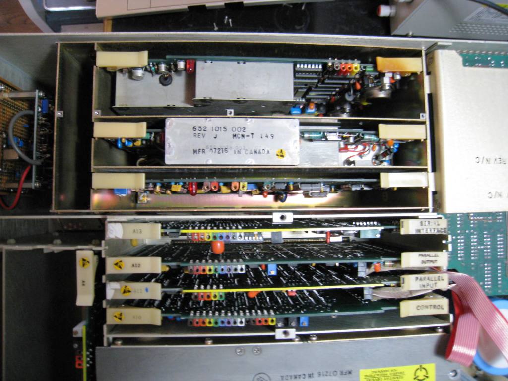
The Control PCB.(left) The Interface PCB.(right)

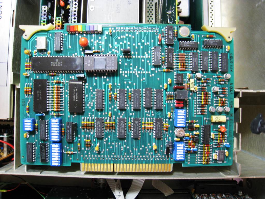
The Interface PCB(left)
The Parallel Interface PCB.(right)
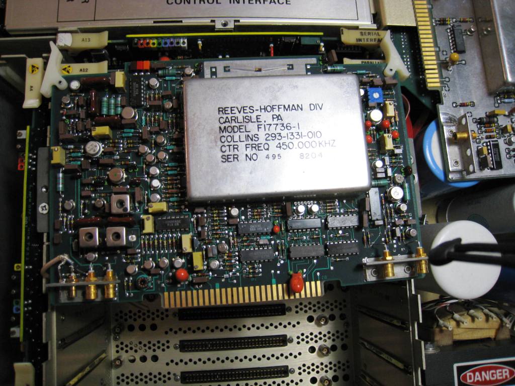
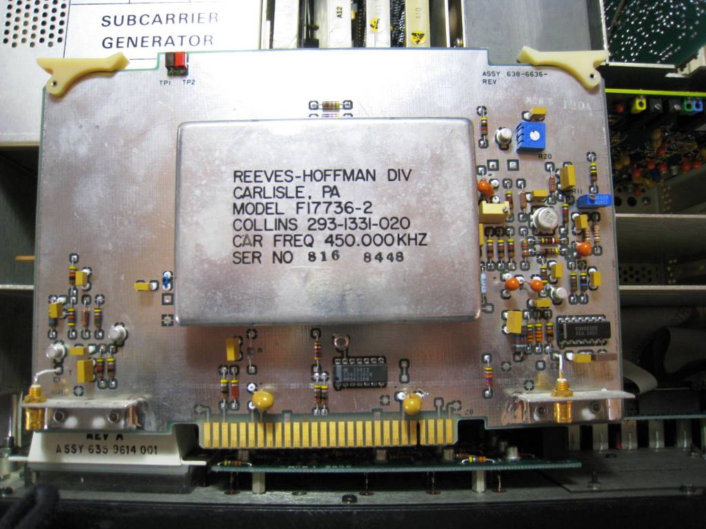
The IF PCB with the 450KHz USB filter.(left)
The PCB of the LSB filter which size is more than four times of the Amateur purpose standard.(right)
HF-8014A to be restored well done.(left) HF-8014A in dock.(right)