


HF-8022
*Click on the photo to see it in a larger size.
Updated : April 10 2009
ROCKWELL COLLINS HF-8022 linear amplifier
Purchased report
The HF-8022 linear amplifier has been purchased for the purpose of my preliminary studying and researching through
the experiment to know the principle of the 208U-3A linear
amplifier to be restored.
It seems that this system have been serving the telephone communication between Florida and islands of the Caribbean
Sea.
Although the unit had been maintained around a half year without any hard troubles, the system is still waiting for
the testing under the full-power output, because I could
not manage the resource for the power supply.
In some day, I would like to experiment with leasing the large power generator to be useful for the maximum output.
In the catalog, the specification introduces the weight of 752Kg to consume 2.5KW in the heater circuit, and 13KW to
be idling and 23KW to operate CW transmitting with 10KW PEP.
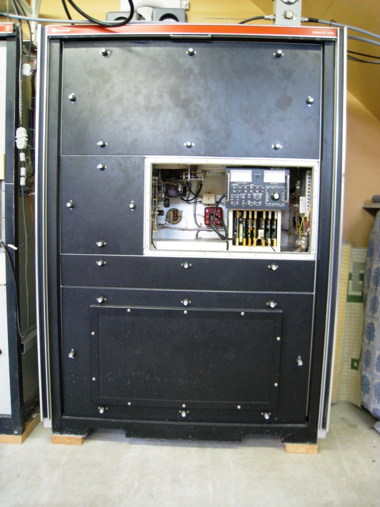
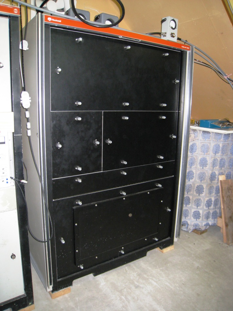
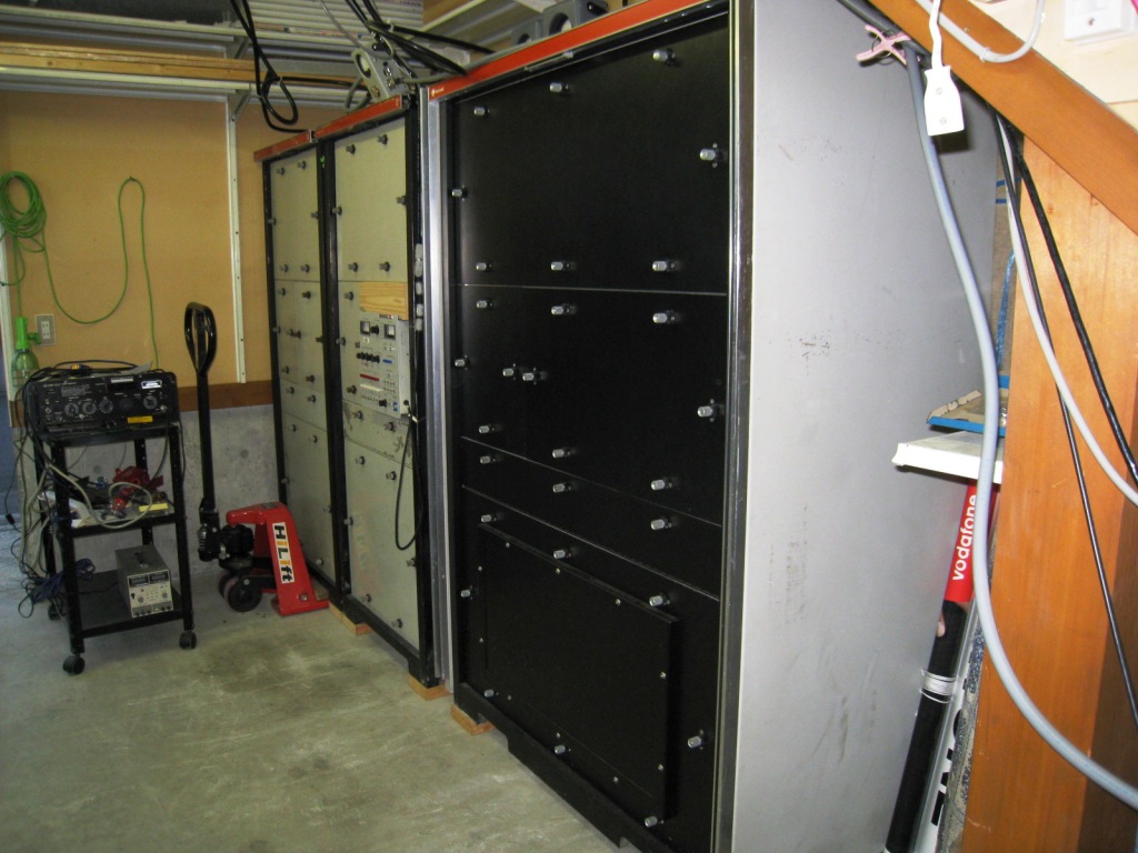
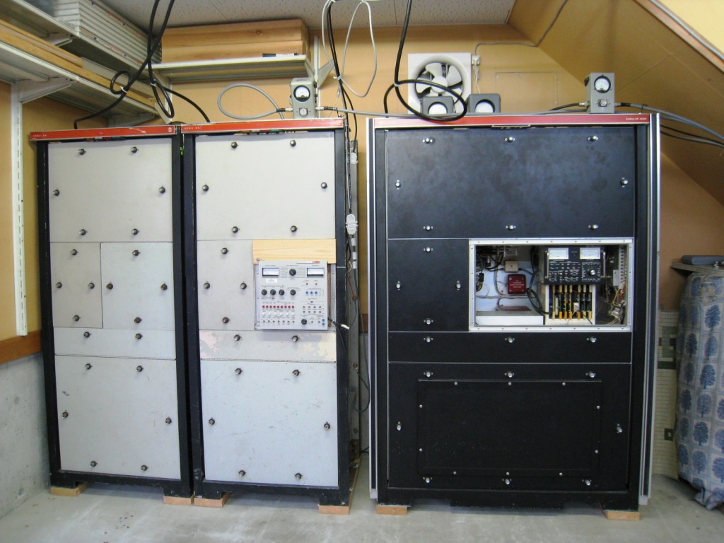
The 208U-3A (left) and the HF-8022 (right) linear amplifiers are parking in the garage.
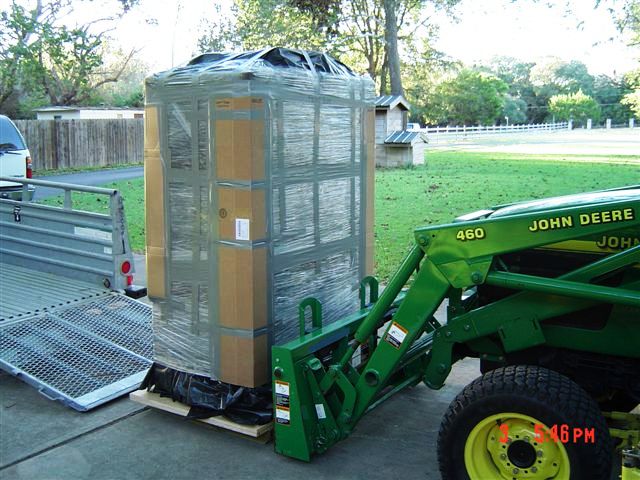
A just arrived unit (left), and the testing panel: TS-8021 component (right)
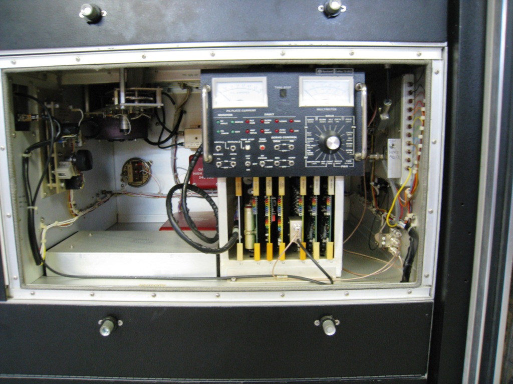
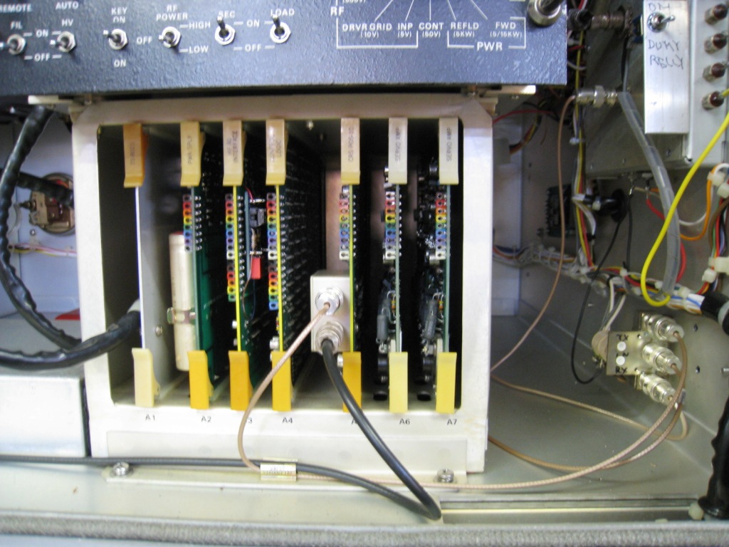
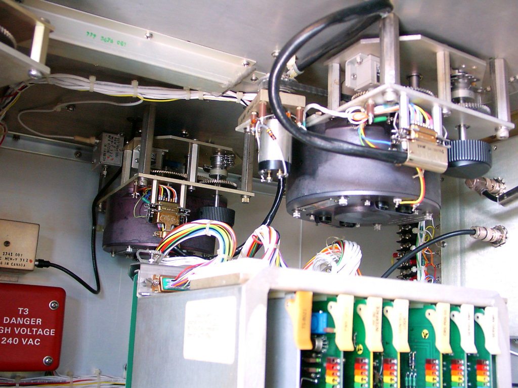
Comparing with the 208U-3A system, the Control boards are more convenient openly to maintain (left).
After removing the driver component,the coil for the resonator circuit can be viewed (right).
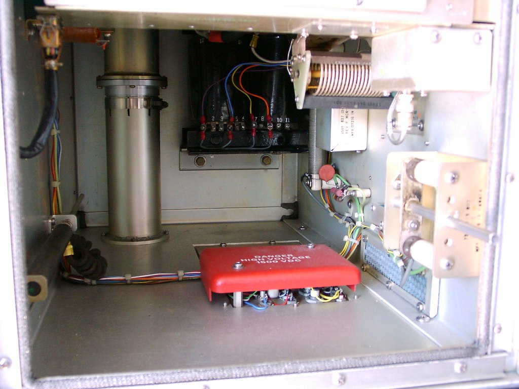
The driver component is configured by three amplified stages that have a grounded-base transistor at the first amplifier, a single tube 4CX350A (upside-down ) at the second amplifier and paralleled twin of the tube 4CX350As at the third amplifier to be featured as the A class operating function (left). The coupling capacitor for the high voltage (right)
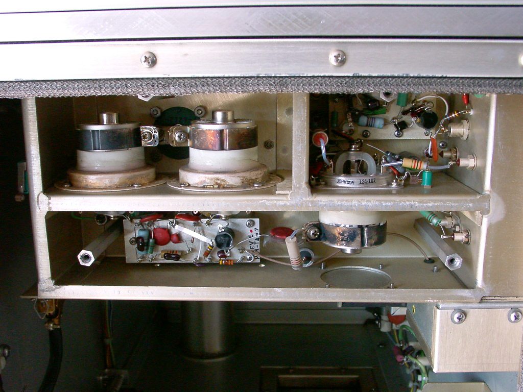
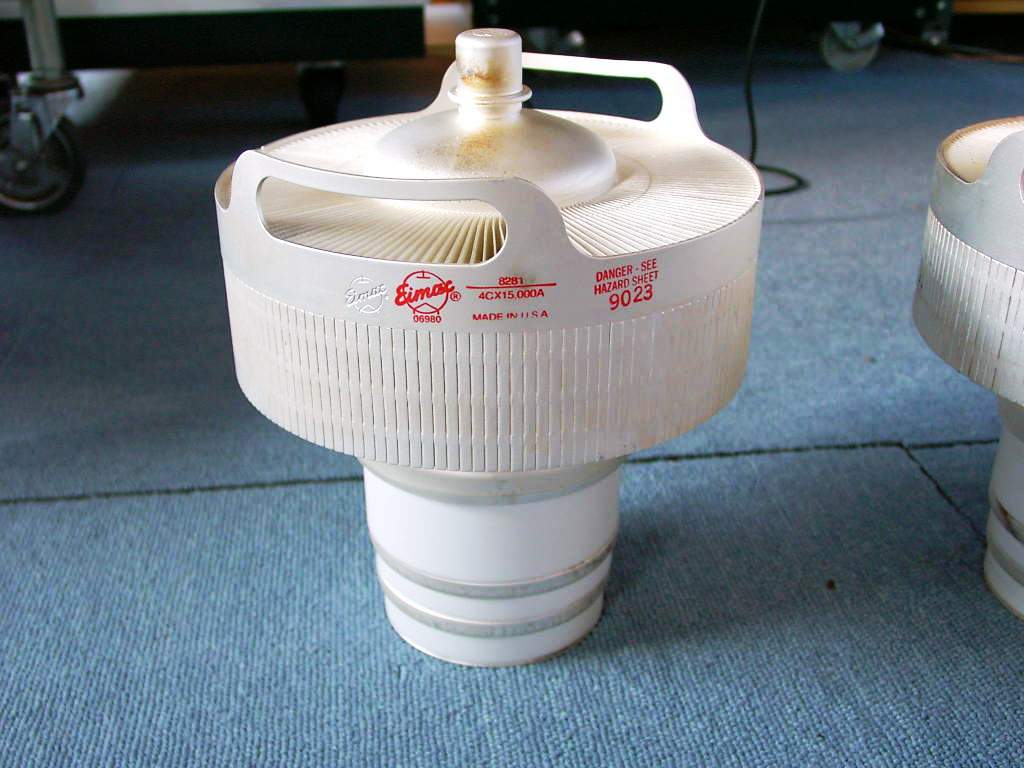
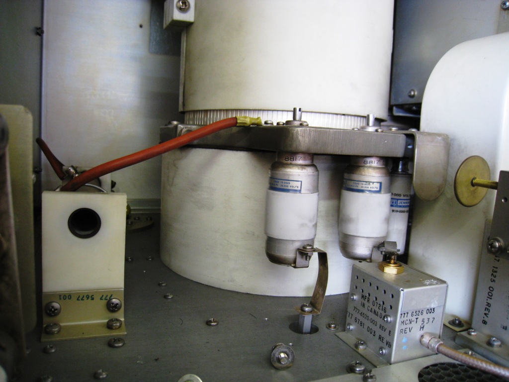
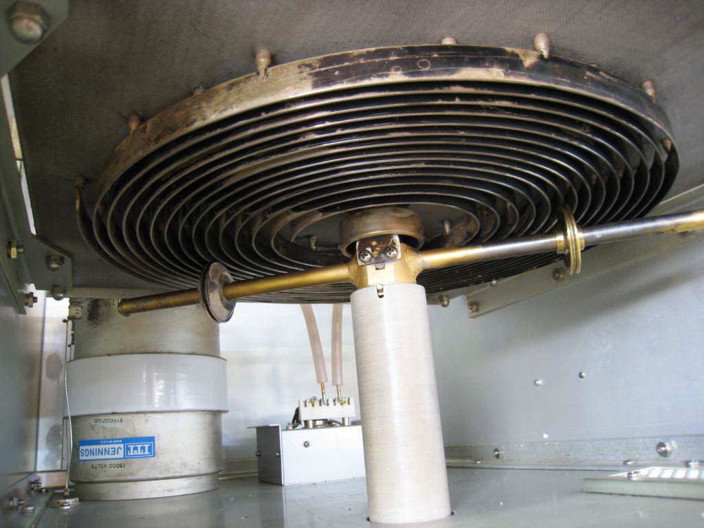
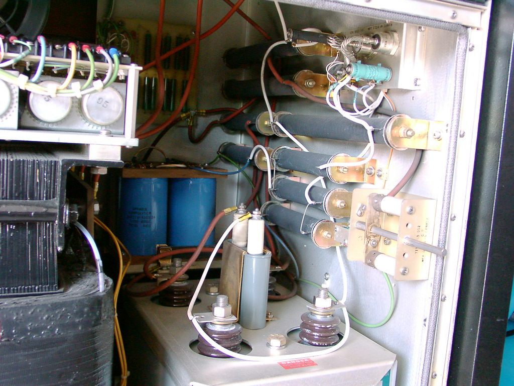
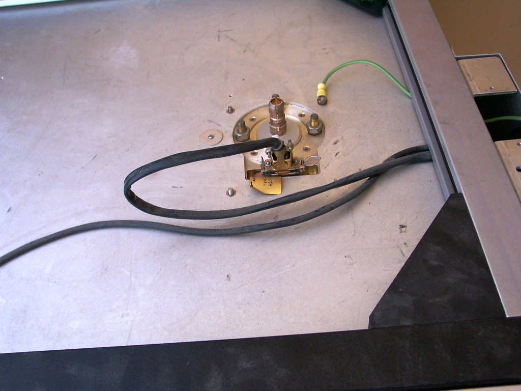
The small vacuum capacitor is to neutralize and adjust for the NF (left). The tube 4CX15000A viewed from the top (right).
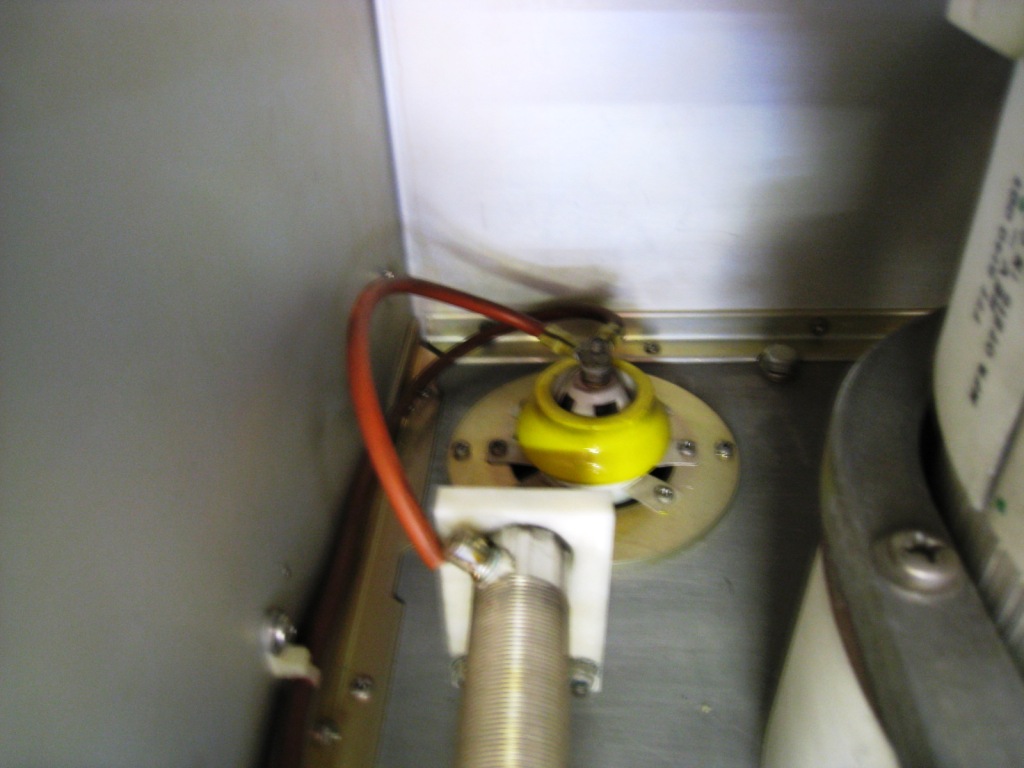
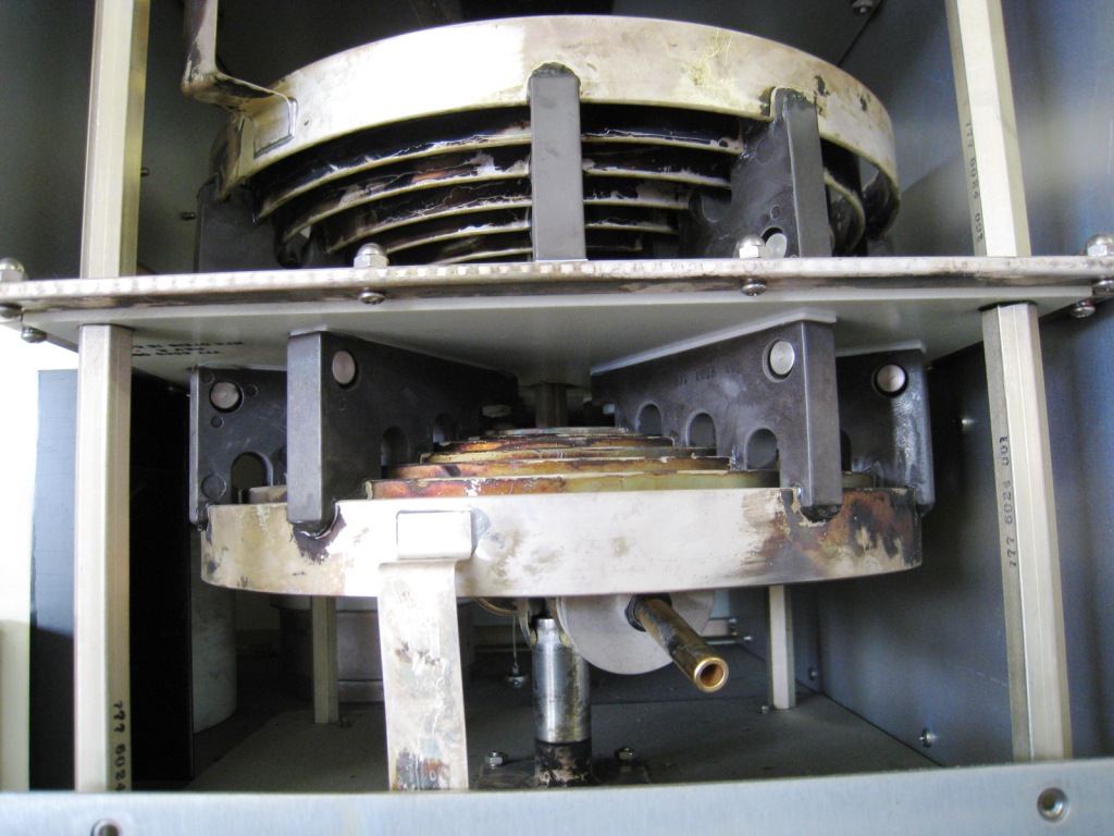
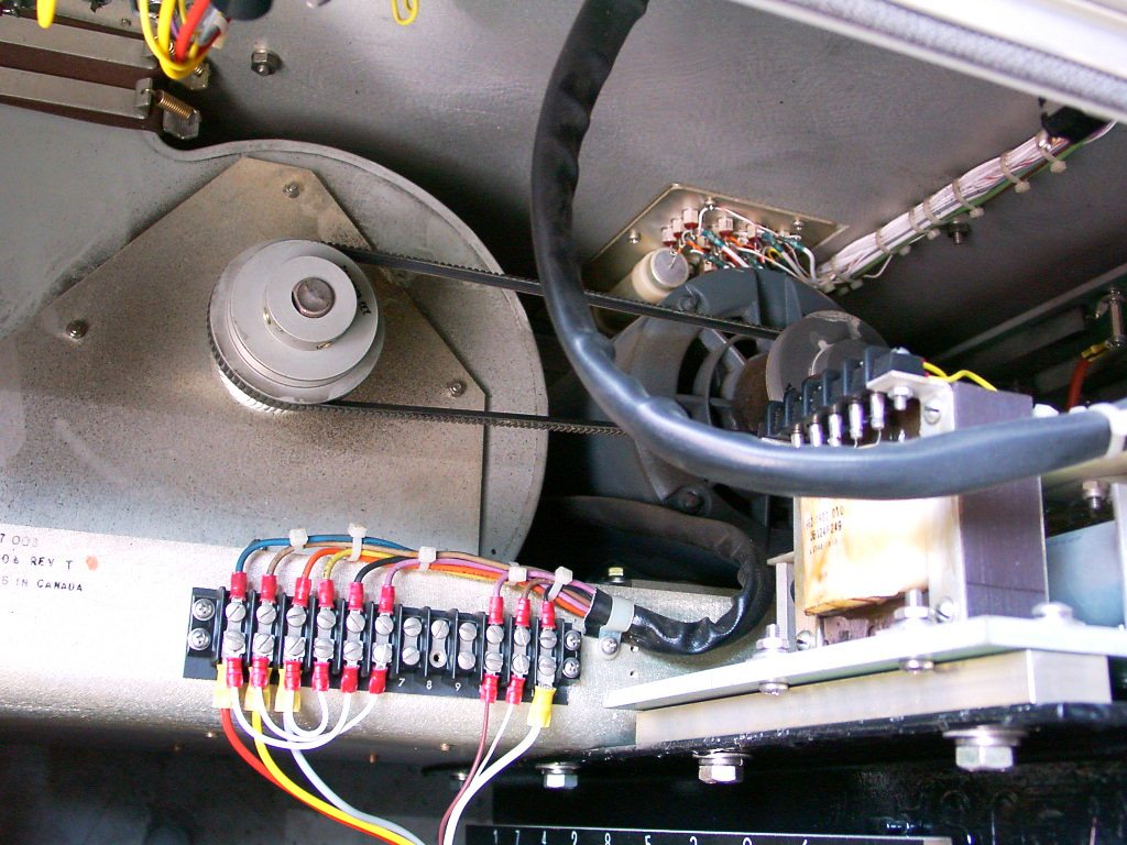
The low-pass filter (left) and the servo-motor to rotate the large vacuum capacitor (right).
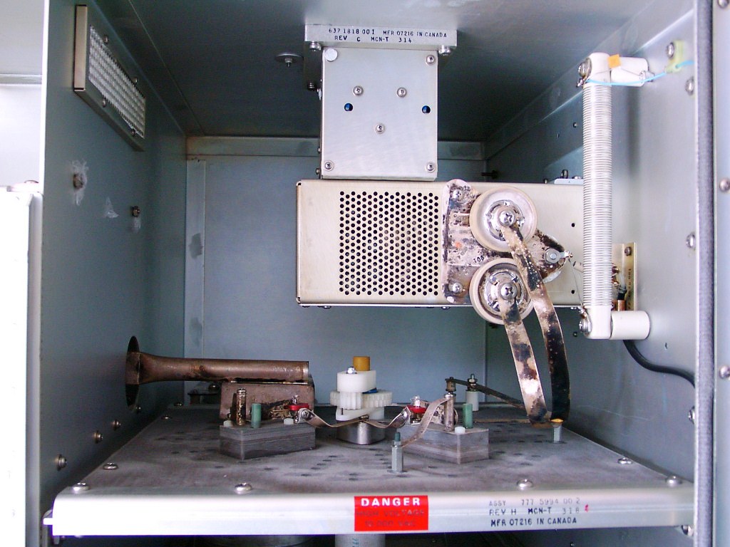
There are several servo mechanisms to rotate large tank coils with knobs to handle manually (left) and the tank coils layered in the upside room (right).
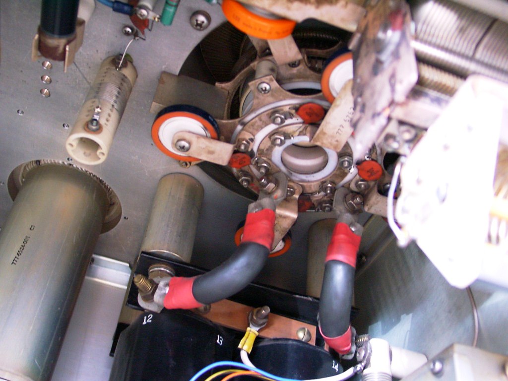
The loading coil (left) and the socket of the final tube connected heater cables with 130A/ 6.3V to be the ultra-current (right).
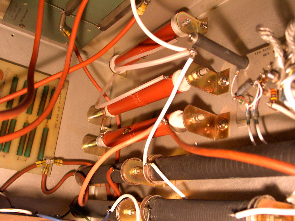
Breeder resisters (left) and the replaced resisters made in domestic because of failure by the burnt disconnection (right).
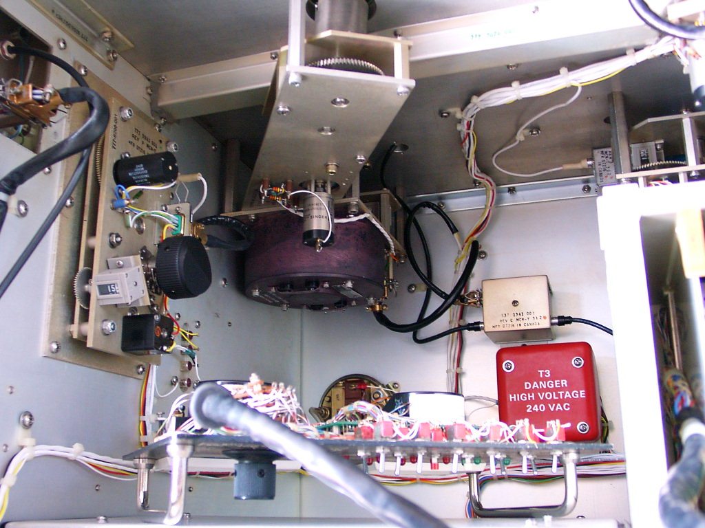
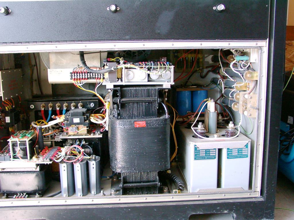
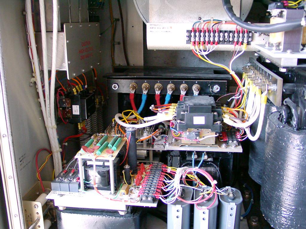
In the power supply component there are several transformers for the stepping-up purpose at the center (left), and larger transformers for the plate 6250V, the screen grid 0V, the grid -1520V and the cathode 1250V (right).

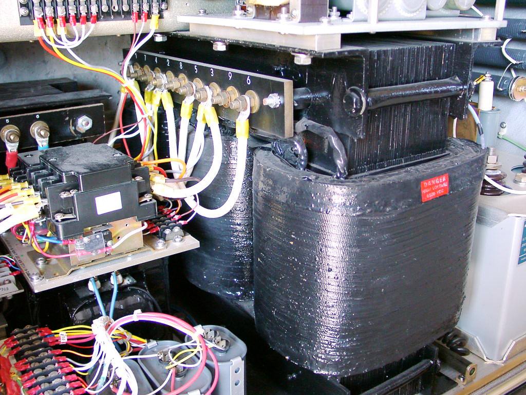
The transformer in the left back corner is for stepping-up and the largest transformer in the center is for the
plate and screen grid.
Both transformers are applying for the input voltage from 198V to 225V and also from 342V to 442V.
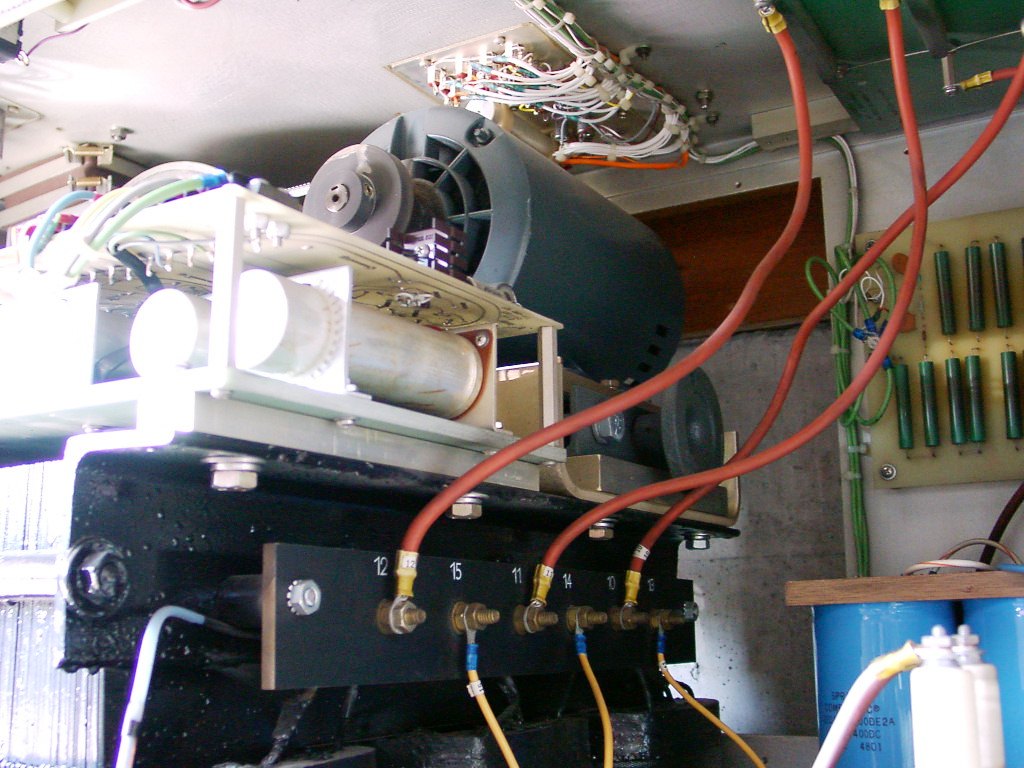
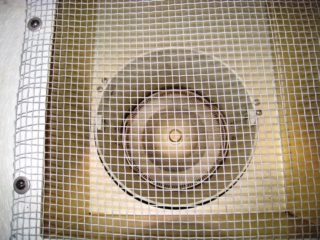
The large centrifugal fan used to run making noises like the circumstance in a small factory (left), and the power supply block for the driver circuit and the control component (right).
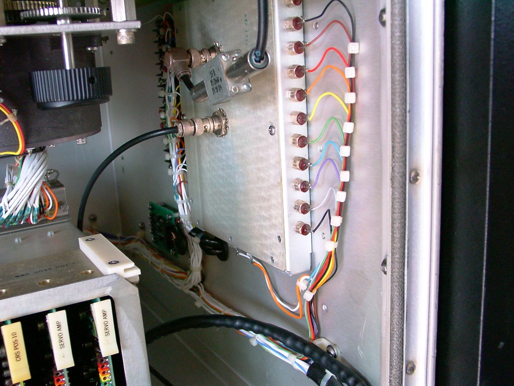
The terminal for the RF output (left), and the injection component of the RF input and the control signal (right).
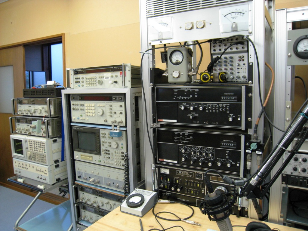
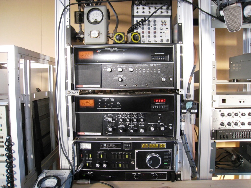
Measurement tools for the experiment and the exciter HF-8014A at a top layer of the rack, the receiver HF-8054A at a second layer, and the receiver WJ-8718A at a third layer.
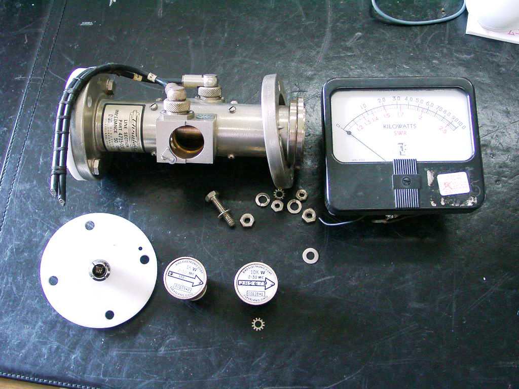
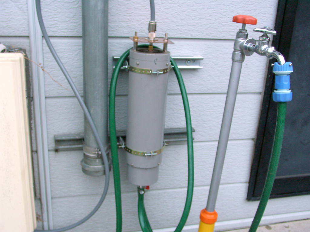
The BIRD power sensor for 50KW and the meter (left) with the dummy load 10KW to be water-cooled piped from a well only during the experiment (right).
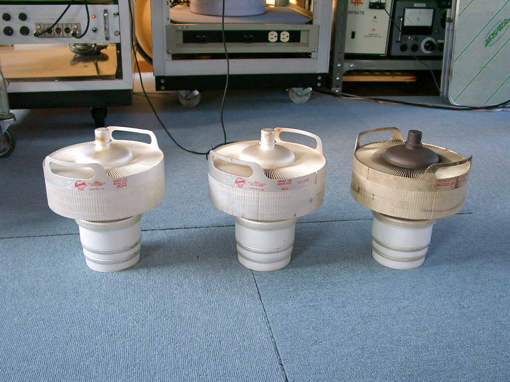
Tube 4CX15000As (from left), and a dumb tube of the initial (right) even though it had outputted around 6KW PEP.