


HP3588A
*Click on the photo to see it in a larger size.
Updated : April 10 2009
Agilent/ HP 3588A Spectrum Analyzer, 10 Hz to 150 MHz
History
I have purchased the quite cheap junk unit from the Middle East through the eBay in the mid September, 2008.
During the check, my heart initially filled with joy because of operating with the displayed CRT clearly at the
powered-on condition.
Then, I have started the procedure of the Self-Tests. As I concerned, the junk has displayed 'FAULT' messages at
several points. I made my mind to repair the unit.
Firstly, I decomposed the unit for washing components and the case in the dirty condition.After aging in several
hours, the Self-Tests has judged the correct functionality from
the junk through calibrating. My heart was feeling good again by the completion of this trial.
Secondly, the unit however indicated the 'FAULT' message again, when I pushed the power switch under the cold
environment in the next day.
Supposed that this problem of the unit would be based on the nature of the temperature in the component.The fault was
however figured yet, during the operation after warming up.
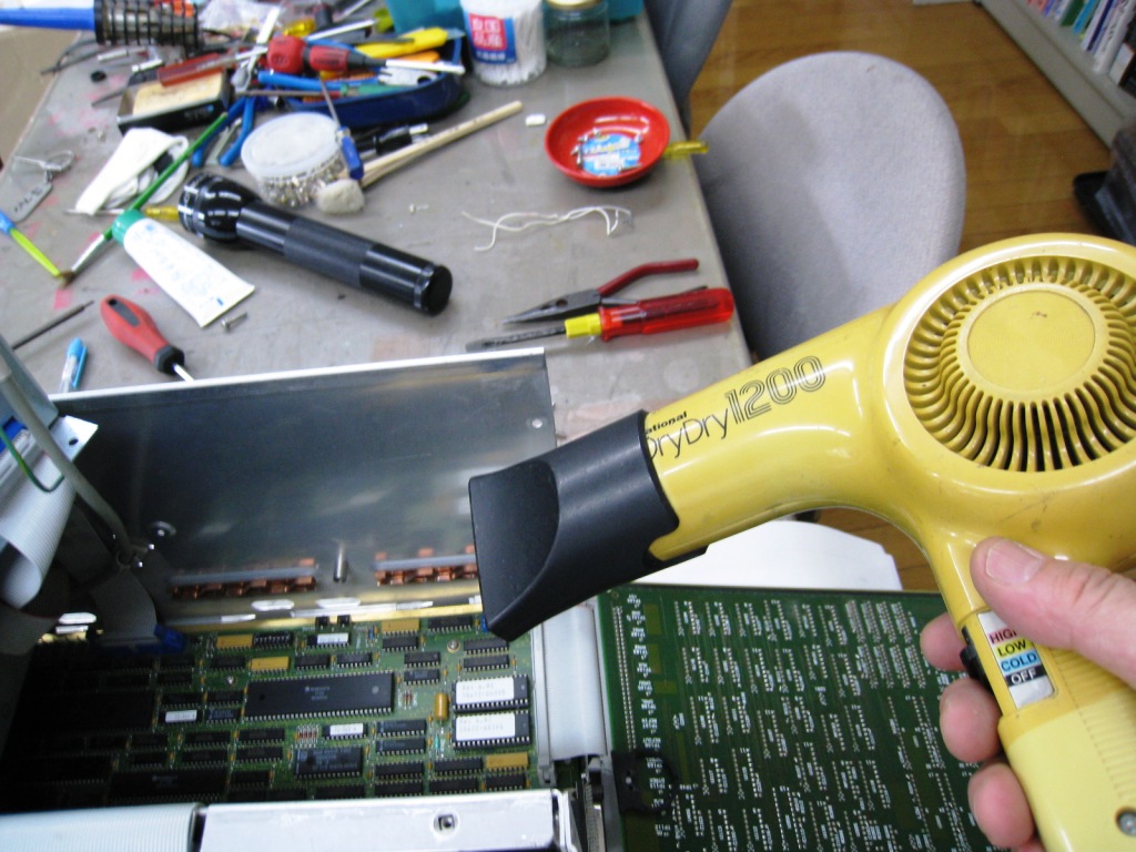
Then, I tried to warm up components by the hair drier and cool down them in the refrigerator.
I found the causes-effect relation between the fault and the temperature. In conclusion, the unit functions correctly
only around 24 degrees centigrade and faults in the condition
under and upper from the 24 degrees centigrade.
Finally, I have started terribly to analyze the description of the English sentences in the manual that does not have
included the schematics, unfortunately because I am not so good
at English.
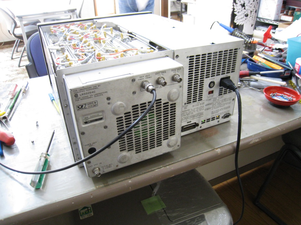
The top view of the unit and the interface cables,(left) the power supply component .(right)

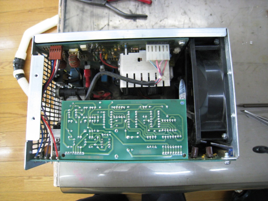
The CPU board,(lift) the Control interface component.(right)
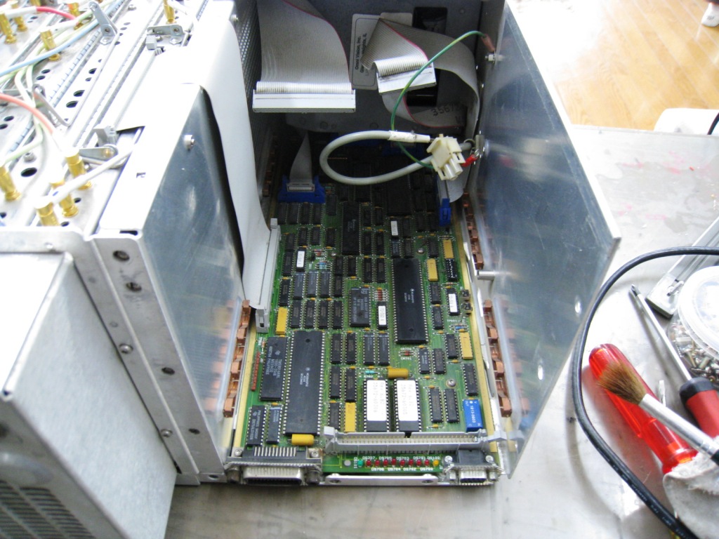

The maintenance and measurement might be easy for us to do under the feature of the flexible inter-connection between
PCBs.
It's the state-of-the-art architecture of HP that has designed well with the better maintainability.

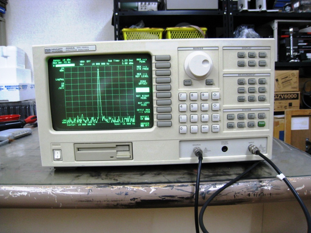
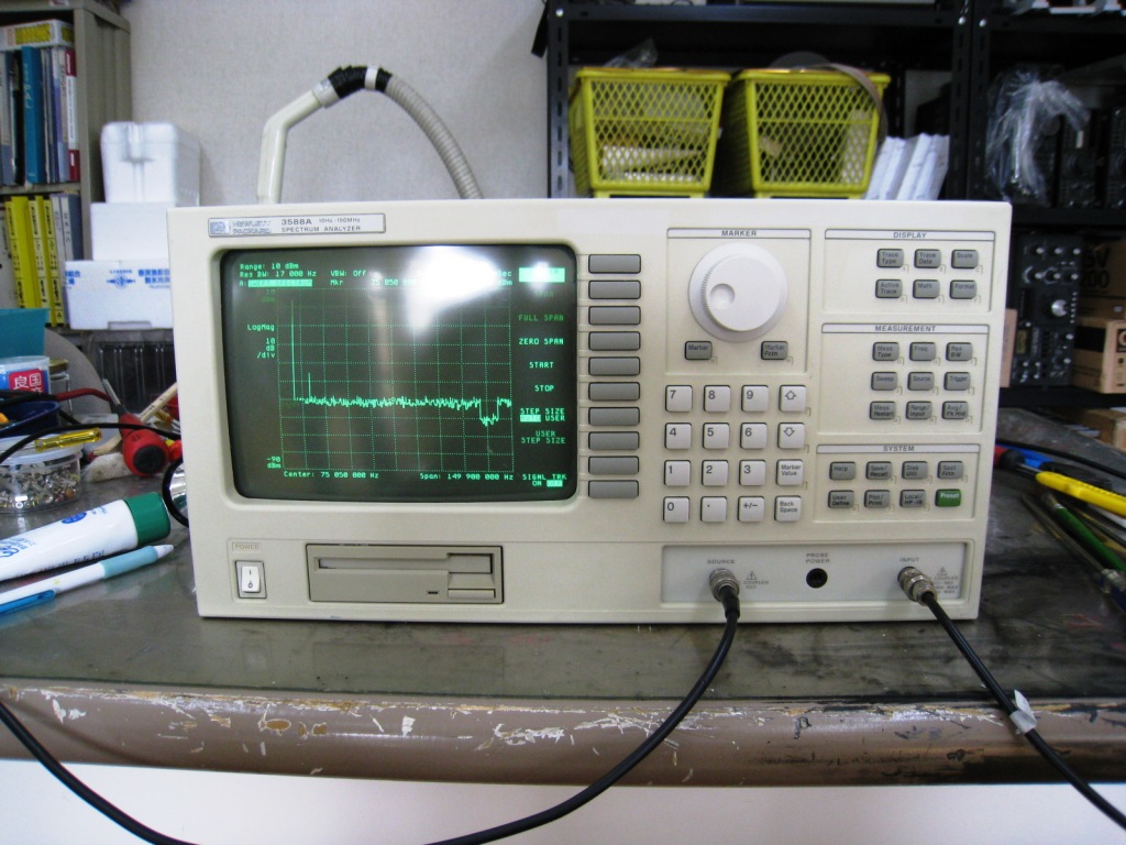
The screen is displaying the erroneous state figure on the frequency response of HP3588A by the injected signal from
the tracking generator.
I could confirm the unstable portion and width of the decreased figure depending on the temperature and the lead time.
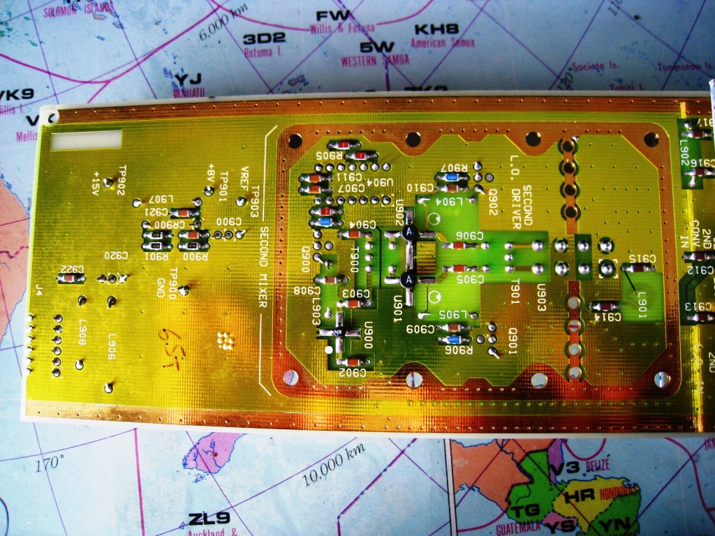
In the left photo, the left-side connector inputs the second IF signal 10,187.5 KHz and transfers to the amplifier to
be gained 10dB.
The amplified signal is mixed by the local oscillator signal, 10MHz, injected through the central connector, and
transfers into the amplifier circuit at the front of the band pass filter,
187.5 KHz in the shielded box of the right-side corner.
Then, the output signal is coming from the right-side connector through the band pass filter.
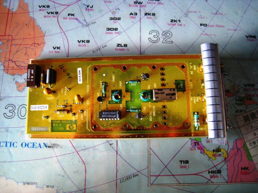
In the right photo, I killed a IC chip during tuning the band pass filter by accident ,because I connected only the
plus voltage into the IC chip, without injecting the minus voltage.
The mistake was happened by my idea considering only the functionality of the RF circuit. If the minus voltage is
ignored, the secondary trouble would be invited.
Fortunately, I could replace it with the attached socket, as the Japanese agent had a stock of the IC package.

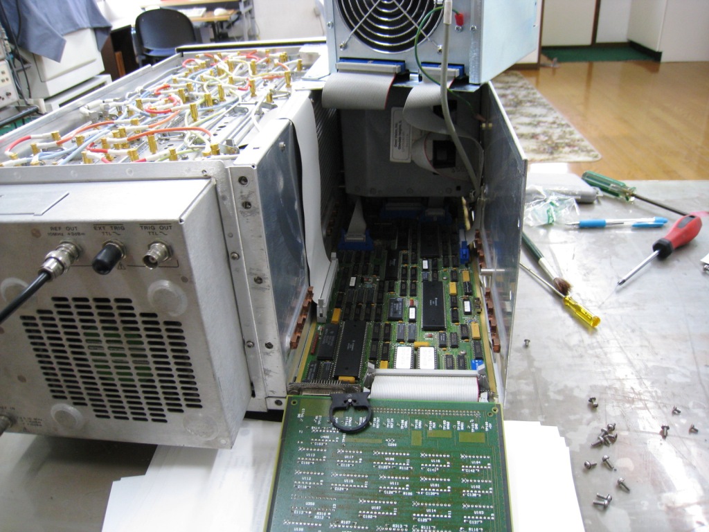
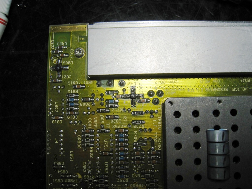
The failed portions of the fault PCB. I needed to spend around two weeks until the completion to specify the failed
point through measuring the level of the signal strength
and the percentage of the amplification using the spectrum analyzer, the signal generator and the oscilloscope under
consulting the manual.
The failure that I found firstly was the malfunction in one of U-902s at the amplifier of the local oscillator signal
on the second mixer stage.
As there was no schematics of the unit, I could not decide which semiconductor was failed, the transistor, the FET or
the MMIC at first.
After tracing the circuit board, I assumed that the failure would be the MMIC because there was no bias bus line on
the board.
But I could not identify the type code of the MMIC because of printed 'A' only..
After searching the internet Web-site, I could confirm the type code of the MMIC might be 'MAV-11SM' in the selling
parts 'A' of the eBay auction.
Again I appreciate the contribution of the internet during my restoration. In order to eliminate the waste time until
the delivery of the won MMIC, I challenged to inspect the correctness of my decision, that is, the malfunction of the
MMIC, with connecting another MMIC of my stock as an alternative.
Finally I replaced two of them from my stocked alternatives in the similar feature.
Although it seemed for my experiment to be successful, I however found the 'FAULT' message still sometimes under
getting better signal level.
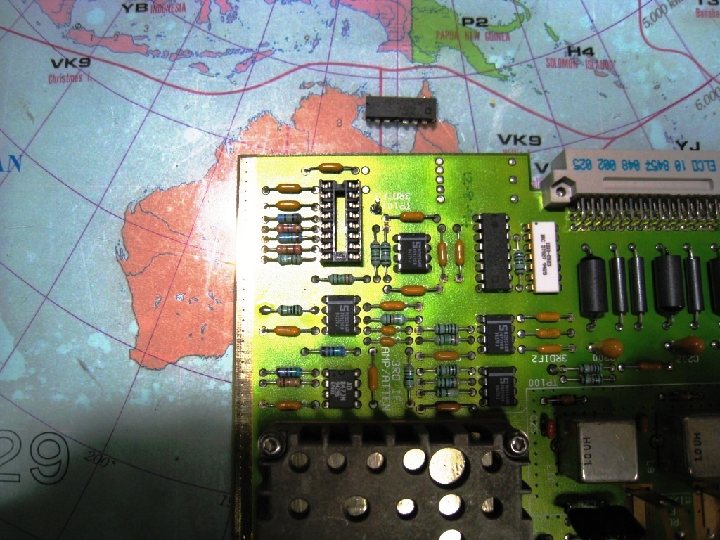
In the left photo, the failure that I confirmed secondly was to be the reduced gain by 10 dB at the 1st mixer circuit
after measuring the signal level.
Firstly I removed the component. The removed PCB was connected to the external power supply, in order to measure the
signal level of each stage separately by the spectrum analyzer with injecting the local oscillator signal 300MHz from
the signal generator.
Then, I found that the failure was the amplifier IC chip of the second stage that was configured by the MMIC (Grove IC
stamped 'A' in the photo).
In this case, only the MMIC which was a same type of MAV-11SM was the wrong parts too. I replaced it by the right MMIC
that was one of replaced MMIC before in the second mixer.
In conclusion, this replacement had been my final correction in this unit because the Self Tests procedure accepted
any operations.
I needed three weeks until fixing the functionality.
In the right photo, it displays the status of the unit through tuning and calibrating once after aging in 24
hours.
I judged that the functionality would be OK under the designed specification, that is, less than 0.5 percent erroneous
rate through the hot-running test during 24 hours.

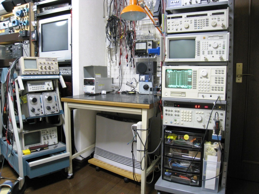
The photo is introducing the view of my new test bench corner that has been graded up into the rack. The frame in a
photo includes the signal generator of Anritsu in the top cage,
the network analyzer of HP, HP3588A, and the two tone typed signal generator, HP3326 in the bottom cage.